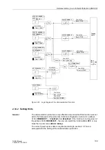
Underexcitation (Loss-of-Field) Protection (ANSI 40)
107
7UM62 Manual
C53000-G1176-C149-3
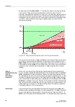
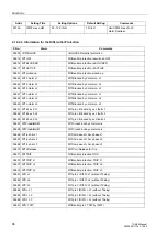
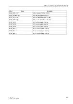
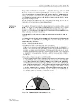
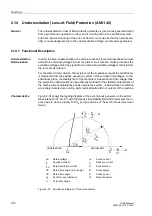
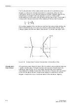
The 7UM62 underexcitation protection provides three independent characteristics
which can be freely combined. As illustrated in Figure 2-52, it is, for example, possible
to model the static machine stability characteristic by means of two partial
characteristics with the same time delays (T CHAR. 1 = T CHAR. 2). The partial
characteristics are distinguished by the corresponding distance from the zero point (1/
xd CHAR. 1) and (1/xd CHAR. 2) the corresponding inclination angle
α
1 and
α
2.
If the resulting characteristic
(1/xd CHAR.1)/
α
1; (1/xd CHAR.2)/
α
2
is exceed (in
Figure 2-52 to the left side), a delayed warning (e.g. by 10 s) or a trip signal are
transmitted. The delay is necessary to ensure that the voltage regulator is given
enough time to increase the excitation voltage.
Figure 2-52
Stator Criterion: Pick–Up Characteristic in Admittance Diagram
A further characteristic (1/xd CHAR.3 /
α
3
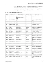
can be matched to the dynamic stability
characteristic of the synchronous machine. Since stable operation is impossible if this
characteristic is exceeded, immediate tripping is required in this case (
time
stage).
Note:
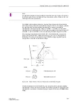
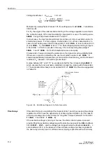
The generator diagram can be visualized in more than one way. Figure 2-51 shows a
form that is quite common at Siemens Power Generation, with a rotation of 90° and
mirroring at the active power axis.
1/xd
Charact. 2
Charact. 3
Characteristic 1
δ
α
3
α
2
α
1
E/U
I/U
1/xd
1/xd
G [p.u.]
B [p.u.]
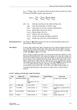
where
G [p.u.]
P S
N
⁄
U U
N
⁄
(
)
2
------------------------
=
Conductance per unit
B [p.u.]
–Q S
N
⁄
U U
N
⁄
(
)
2
------------------------
=
Susceptance per unit
CHAR.1
CHAR.2
CHAR.3


