


Functions
94
7UM62 Manual
C53000-G1176-C149-3
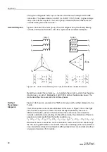
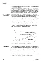
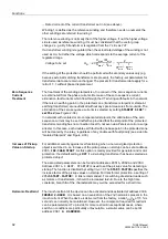
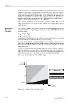
the parameter
. This branch considers current-proportional
error currents. These are mainly transformation errors of the main CTs and,
especially, the differential currents which may occur in the final tap changer positions
due to the transformer regulation range. This branch of the characteristic limits the
stabilization area. The preset slope of 0.25 should be sufficient for regulating ranges
up to 20 %. If the transformer has a larger regulated range, the slope must be
increased accordingly.
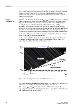
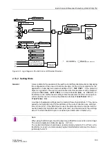
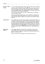
Figure 2-44
Parameters Determining the Shape of the Tripping Characteristic
The second branch produces a higher stabilization in the range of high currents which
may lead to current transformer saturation. Its base point is set at address
and is referred to the rated power transformer current. The slope is
set at address
. The stability of the relay during current transformer
saturation can be influenced by this parameter. A higher slope results in a higher
stability.
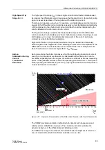
Add-on
Stabilization During
Current
Transformer
Saturation
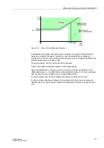
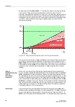
Where very high currents flow through the protected object during external short-
circuits, an add-on stabilization takes effect that is set at address
(stabilization in case of saturation). Please note that the stabilizing current is
the arithmetical sum of the currents entering and leaving the protected zone, i.e. that
it is twice the actually flowing current. The default setting of
4.00 I/InO
should be
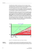
kept. The maximum duration of the add-on stabilization is set at address
2056
in multiples of one cycle. This time is the maximum duration of the blocking
after leaving the add-on stabilization area in case of high-current external faults. The
setting depends, for instance, on the disconnecting time of the upstream protection.
The default setting
15 *1P
is a good value.
Time Delays
In special cases it may be advantageous to delay the trip signal of the differential
protection with an additional time stage. The time delay
2026
is started
when an internal fault in the generator or the motor has been detected.
2036
is the time delay for the trip stage I DIFF>>. A separate time stage is provided
1
2
3
4
5
6
7
8
9
10 11 12
13 14 15 16 17 18
1
2
3
4
5
6
7
8
9
10
2031
I–DIFF>>
2021
I–DIFF>
2044
BASE POINT 2
BASE POINT 1
2042
Trip area
I
stab
I
NObj
---------------
I
diff
I
NObj
---------------
Block area
2043
SLOPE 2
2041
SLOPE 1
EXF–STAB
2056
Add-on stabilization
b
c
d
a


