Breaker Failure Protection (ANSI 50BF)
227
7UM62 Manual
C53000-G1176-C149-3
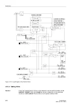
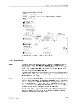
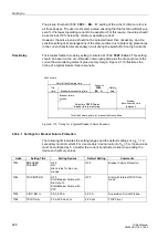
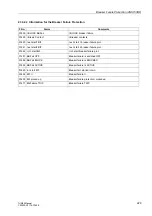
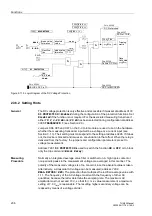
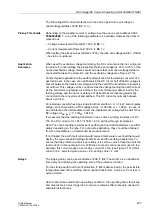
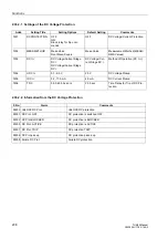
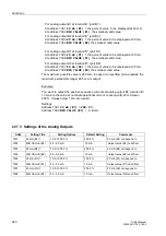
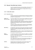
Figure 2-109 Logic Diagram for the Breaker Failure Protection
2.34.2 Setting Hints
General
The breaker failure protection function is only effective and available if it has been
assigned at address
to
Side 1
or
Side 2
during
configuration of the protective functions. Set
Disabled
if the function is not required.
Address
is used to switch the function
ON
or
OFF
, or to
block only the trip command (
Block Relay
).
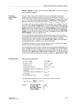
The current measurement for the circuit breaker failure protection can be performed
either at side 1 (inputs I
L, S1
) or at side 2 (inputs I
L, S2
). It is recommended to use the
terminal-side set of CTs, i.e. side 1.
Criteria
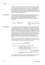
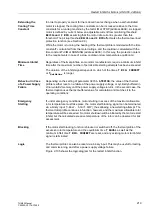
The parameter
serves to select the OFF criterion of the internal
pickup. It can be implemented by reading the switching statuses of the corresponding
output relays BO12 (
=
BO12
) or by a logic link created in CFC
(=
CFC
) (annunciation
1442
”
”). The internal source can be
completely deactivated (
=
OFF
). In this case the breaker failure
protection can only be initiated by external sources via binary input.
Note: Be aware that only the potential-free binary output BO12 (Relay R12) can be
used for the breaker failure protection. This means that trippings for the network
breaker must be configured to this binary output.
&
FNo. 01423
FNo. 01422
FNo. 01403
FNo. 01441
Tripping
matrix
CFC
OFF
&
FNo. 01452
FNo. 01471
FNo. 01444
OR
FNo. 01455
FNo. 01443
BO 12 binary output (Relay R12), potential-free
I
>TRIP
U>>TRIP
f<TRIP
Masking
HW model
of relays
Bin.Outp.12
Device-internal protective functions
FNo. 01442 (via CFC)
”0”
TMin
TRIP CMD
OR
OR

