


3 Installation and Commissioning
340
7UM62 Manual
C53000-G1176-C149-3
Secondary Test of
the Differential
Protection
A test set with 6 current outputs is recommended for secondary testing. This section
gives you hints how to proceed if less current sources are available. The test current
can be injected individually for each winding, thus simulating each time a transformer
fault with single-ended infeed.
The preset parameter for
as pick-up value (address
) applies for three
or two-phase testing. The pickup value for single-phase testing depends on the
method the zero sequence current is treated within the relay:
If the zero sequence current is eliminated, then the pickup value is increased to 1.5
times the set value because of the elimination of the zero sequence current; this
corresponds to conventional circuitry when the current is fed in via matching
transformers.
If the zero sequence current is not eliminated (isolated starpoint), the pickup value
corresponds to the setting value
even during single-phase testing.
Checking the pickup value is performed by slowly increasing the test current for each
winding with the test set. Tripping occurs when the pickup value, converted according
to the matching factor, is reached. When the test current falls below approximately 0.7
times the pickup value, the relay drops off.
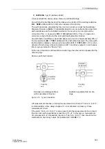
In the method described above, the pickup values for single-ended infeed are tested.
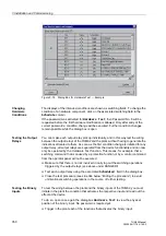
It is also possible to check the entire characteristic. Since trip current and restraint
current cannot be fed in separately (they can, however, be read out separately in the
test measurements), a separate test current has to be applied to each of the two
windings.
When testing with the operational parameters, it should be noted that the setting value
IDIFF >
refers to the rated current of the transformer, i.e. current which results from:
with S
N Transf
– MVA rating of transformer
U
N Winding
– Rated voltage of the respective winding; if a winding is regulated,
then the parameterized voltage according to Section 2.11.2.2 applies
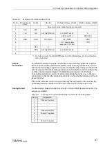
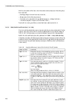
Furthermore, the pickup values can change with single -and two-phase testing
depending on the vector group of the protected transformer; this corresponds to
conventional circuitry, when currents are applied via matching current transformers.
Table 3-23 shows these changes as a factor k
VG
depending on the vector group and
the type of fault, for three-phase transformers.
In order to obtain the pickup value, the setting value
(parameter address
) must be multiplied by the factor
I
N Transf
S
N Transf
MVA
]
[
1000
⋅
3 U
⋅
N Winding
kV
]
[
------------------------------------------------------------
=
for three-phase transformers
[A]
I
N Transf
I
N CT (primary)
-----------------------------------
k
VG
⋅


