3 Installation and Commissioning
350
7UM62 Manual
C53000-G1176-C149-3
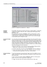
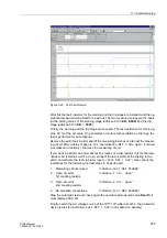
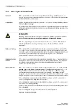
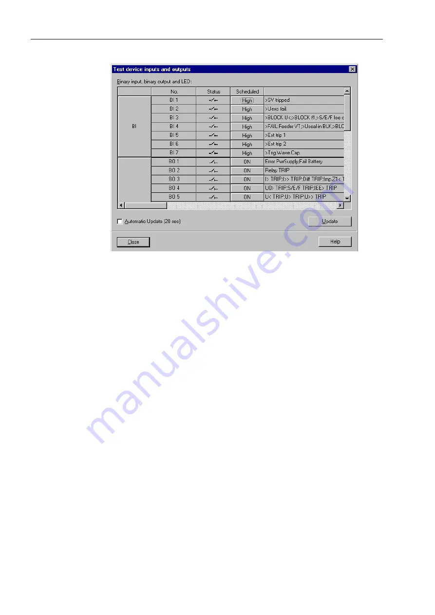
Figure 3-18
Dialog Box for Hardware Test — Example
Changing
Hardware
Conditions
The displays of the intended conditions are shown as switching fields. To change the
condition of a hardware component, click on the associated switching field in the
Schedule
column.
If the password was activated for
Hardware Test
, then Password No. 6 will be
requested before the first hardware modification is allowed. Only after entry of the
correct password a condition change will be executed. Further condition changes
remain possible while the dialog box is open.
Testing the Output
Relays
You can make each output relay pick up individually, and in this way test the wiring
between the output relays of the 7UM62 and the plant, without having to generate the
indications allocated to them. As soon as the first condition change is initiated for any
output relay, all output relays are separated from the device functionality and can now
only be operated by the Hardware Test function. This means, for example, that a
switching command that is caused by a protection function or by a control command
from the operator panel will not be executed.
G
Make sure that there is no risk involved in carrying out the switching operations
triggered by the output relays (see above under DANGER!).
G
Test each output relay using the associated
Scheduled
field in the dialog box.
G
Close the test procedure (see side title below “Ending the procedure”) to avoid
unintentional switching operations in the course of further testing.
Testing the Binary
Inputs
To test the wiring between the plant and the binary inputs of the 7UM62, you must
initiate in the plant the condition that activates the respective input and read out the
effect at the device.
To do so, open once again the dialog box
Hardware Test
to view the physical
position of the binary input. No password is required yet.
G
Trigger in the plant each of the functions that activates the binary input.

