3 Installation and Commissioning
336
7UM62 Manual
C53000-G1176-C149-3
3.2
Checking Connections and System (Plant) Integration
3.2.1
Checking the Data Connections of Serial Interfaces
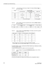
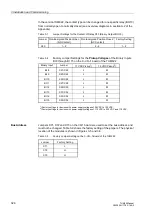
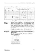
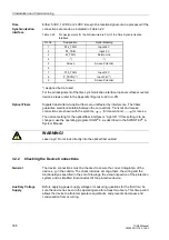
The following tables shows the pin-assignments for the various serial interfaces and
for the time synchronization interface of the device.
Operator Interface
at Front
When the recommended communication cable is used, correct connection between
the SIPROTEC
®
device and the PC is automatically ensured. See the Appendix, Sub-
section A.1 for an ordering description of the cable.
System Interface
When a serial interface of the device is connected to a a central control system
(SCADA), the data connection must be checked. A visual check of the transmit
channel and the receive channel is important. In the RS232 and the FO interface,
each connection is dedicated to one transmission direction. The data output of one
device must be connected to the data input of the other device, and vice versa.
The data cable connections must conform to DIN 66020 and ISO 2110 (see also Table
3-20):
−
TxD
data transmit
−
RxD
data receive
−
RTS
request to send
−
CTS
request to send
−
GND
signal/chassis ground
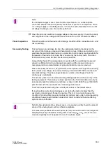
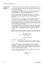
The cable screen is to be grounded at both ends. In environments with extremely high
electromagnetic interference, the EMC immunity can be improved by running the GND
conductor as a separate, individually screened wire pair.
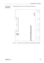
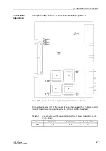
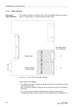
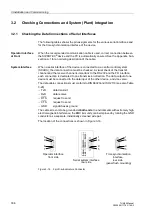
The location of the connections is shown in Figure 3-16.
Figure 3-16
9 pin D-subminiature Connector
P-
Sl
av
e
AM
E
R
S232
R
S232-
FO
RS
48
5
1
6
5
9
rear side
5
9
1
6
Operator interface
front side
1
6
5
9
Serial system interface
Time synchronization
interface
rear side
(panel flush mounting)

