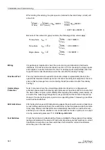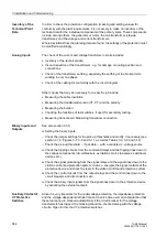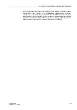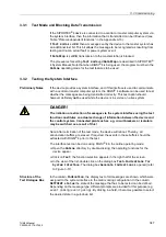
3.2 Checking Connections and System (Plant) Integration
337
7UM62 Manual
C53000-G1176-C149-3
.
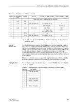
*) Pin 7 also can carry the RS 232 RTS signal to an RS 485 interface. Pin 7 must therefore
not be connected!
RS 485
Termination
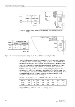
The RS 485 interface is capable of half-duplex mode with the signals A/A’ and B/B’
with a common relative potential C/C’ (GND). Verify that only the last device on the
bus has the terminating resistors connected, and that the other devices on the bus do
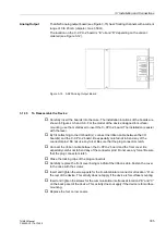
not. The jumpers for the terminating resistors are on the interface card mounted on the
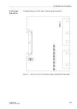
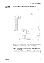
C–CPU–2 board. Refer to Figure 3-13 (RS485) and to Figure 3-14 (Profibus).
Terminating resistors can also be implemented outside the device (e.g. in the plug
connectors). In that case the terminating resistors provided on the interface card must
be switched out.
If the bus is extended, make sure again that only the last device on the bus has the
terminating resistors switched-in, and that all other devices on the bus do not.
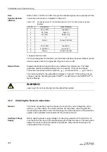
Analog Output
The two analog values are output as currents on a 9-pin DSUB female connector. The
outputs are isolated.
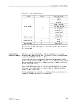
Table 3-20
Installation of the D-Subminiature Ports
Pin No.
PC Interface at
Front
RS 232
RS 485
Profibus DP Slave, RS 485
DNP3.0, Modbus, RS485
1
Screen (with screen ends electrically connected)
2
RxD
RxD
–
–
–
3
TxD
TxD
A/A’ (RxD/TxD–N)
A/A’ (RxD/TxD–N)
A
4
–
–
–
CNTR–A (TTL)
RTS (TTL)
5
GND
GND
C/C’ (GND)
C/C’ (GND)
GND1
6
–
–
–
+ 5 V voltage supply
(max. load < 100 mA)
VCC1
7
–
RTS
–*)
–*)
–
8
–
CTS
A/A’ (RxD/TxD–N)
A/A’ (RxD/TxD–N)
B
9
–
–
–
–
–
Table 3-21
Pin Assignment of the DSUB Female Connector for the Analog Output
Pin No.
Designation
1
Channel 1 positive
2
–
3
–
4
–
5
Channel 2 positive
6
Channel 1 negative
7
–
8
–
9
Channel 2 negative


