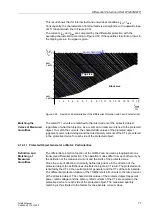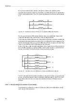
Differential Protection (ANSI 87G/87M/87T)
79
7UM62 Manual
C53000-G1176-C149-3
Mismatching of
CTs
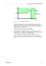
Differences in the matching of CTs to the transformer rated current are not
uncommon. These differences result in an error that leads to a differential current.
Voltage Control by
Tap Changers
Voltage control tap changers (usually in-phase regulators) change the transformation
ratio and the rated current of the transformer. They cause mismatching of the CTs and
thus a differential current.
Inrush Current
Transformers may absorb on power-up considerable magnetizing currents (inrush
currents) that enter the protected zone but do not leave it. They act therefore like fault
currents entering on one side.
The inrush current can amount to a multiple of the rated current and is characterized
by a considerable 2nd harmonic content (double rated frequency) which is practically
absent in the case of a short-circuit.
Overexcitation
(Overflux)
Where a transformer is operated with an excessive voltage, the non-linear
magnetizing curve leads to increased magnetizing currents, which cause an additional
differential current.
Vector Group
Depending on their application, transformers have different vector groups, which
cause a shift of the phase angles between the primary and the secondary side.
Without adequate correction, this phase shift would cause a differential current.
The following paragraphs describe the main functional blocks of the differential
protection that allow to control the above influences.
Matching the
Values of Measured
Quantities
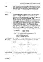
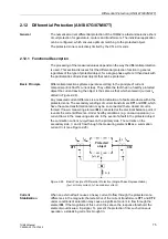
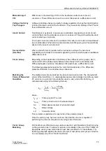
The digitized currents are matched the transformer rated current. The characteristic
values of the transformer, i.e. rated apparent power, rated voltages and primary rated
CT currents, are entered in the protective device, and a correction factor k
CT
is
calculated according to the following formula:
where
I
p, CT
-
Primary rated CT current
I
N,Obj.
-
Primary rated current of protected object
S
N
-
Rated apparent power of protected object
U
N
-
Rated voltage
k
CT
-
Correction factor
This correction is performed for each side of the protected object.
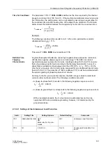
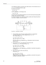
Once the vector group has been entered, the protective device is capable of
performing the current comparison according to fixed formulae.
Vector Group
Matching
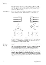
Unit transformers often have a wye-delta connection, with the delta connection being
on the generator side. To allow a maximum of versatility in the use of the 7UM62, all
imaginable vector group combinations have been provided for in the software. The
following paragraph explains the basic principle of numerical vector group correction
in an exemplary way for a Y(N)d5 transformer.
k
CT
I
p, CT
I
N,Obj.
---------------
I
p, CT
3 U
N
⋅
⋅
S
N
--------------------------------------
=
=


