


3.4 Primary Commissioning Tests with the Generator
365
7UM62 Manual
C53000-G1176-C149-3
Calibrating the
Impedance
Protection
Set impedance protection (address
) to
IMPEDANCE PROT.
=
Block relay
:
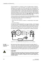
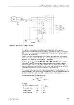
With the primary plant voltage-free and earthed, install a three-pole short-circuit bridge
which is capable of carrying rated current (e.g. earthing isolator) to the primary side of
the unit transformer.
Start-up machine and slowly excite to 20 % of rated machine current.
Note on Testing
A test with about 20 % of the rated generator current is sufficient for checking the
transformer connections and the operational measured values. If the relative short-
circuit voltage of the transformer is small, the voltage values measured are very low,
so that it may be necessary to increase the generator current somewhat. A test with
the full rated generator current is only required for the quantitative calibration of the
impedance protection (e.g. for calibrating the transformer u
K
).
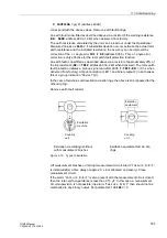
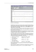
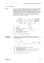
The relay calculates from the currents and voltages the impedance between the point
of installation (voltage transformers) and the short-circuit bridge, i.e. normally the
short-circuit impedance of the unit transformer. Read out the reactance and resistance
values in the measured values. Note that the secondary values depend on the rated
relay current, 1 A or 5 A. In the case of the transformer impedance, the following
results:
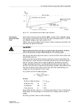
Primary transformer impedance:
with
u
sc
- percent impedance voltage of transformer
U
N
- rated voltage of transformer
S
N
- rated apparent power of transformer
In secondary values:
with
N
CT
- current transformer ratio
N
VT
- voltage transformer ratio
If substantial deviations or wrong sign occur, then the voltage transformer connections
are incorrect.
After shutdown and de-excitation of the generator, and removal of the short-circuit
bride, the short-circuit tests are completed. No further tests are required for
unbalanced load protection, overcurrent time protection, thermal overload
protection, impedance protection and out-of-step protection.
Switch the overcurrent time protection and the impedance protection operative
(address
:
=
ON
resp. address
=
ON
, address
:
=
ON
). They serves from now on as short-circuit protection. If
used, the I>> stage (address
1301
O/C I>>
=
ON
), the thermal overload protection
(address
:
=
ON
), the unbalanced load protection (address
:
=
ON
) and the out-of-step protection (address
=
ON
) can be switched to be operative. Otherwise, they are set to
OFF
.
DANGER!
Primary measurements must only be carried out with the machine at stand–still
on disconnected and earthed equipment of the power system.
Z
T prim
u
sc
U
N
2
S
N
----------
⋅
=
Z
T sec
Z
T prim
N
CT
N
VT
-----------
⋅
u
sc
U
N
2
S
N
----------
N
CT
N
VT
-----------
⋅
⋅
=
=


