3 Installation and Commissioning
386
7UM62 Manual
C53000-G1176-C149-3
3.4.10 Tests with the Generator Connected to the Network
3.4.10.1 Checking the Correct Connection Polarity
The following test instructions apply to a synchronous generator.
Run up generator and synchronize with network. Slowly increase driving power input
(up to approximately 5%).
The active power is read out under the operational measured values (percent values)
as a positive active power P in percent of the rated apparent power S
N
.
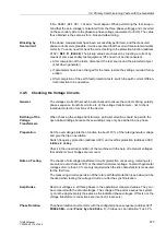
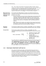
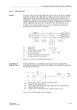
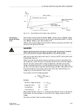
If a negative active power value should be read out, then the actual polarity
relationship between current transformers and voltage transformers does not accord
with the polarity parameterized under address
(
Yes
/
No
) or
a wrong setting has been selected for address
Generator
/
Motor
). Re-parameterize address
. If the power reading is still incorrect, the fault
must be in the instrument transformer connections (e.g. cyclic exchange of phases):
−
Fix faults of the transformer lines (current and/or voltage transformers); observe for
this the safety rules!
−
Repeat test.
3.4.10.2 Measurement of Motoring Power (Reverse Power) and Angle Error Correction
For a generator, leave the reverse power protection and the forward active power
supervision switched to
OFF
for the moment. This function and the following
measurements are not required for motors.
The motoring power is – as an active power – almost constant and independent of the
reactive power, i.e. independent of the excitation current. However, the protection
relay may calculate different active power values dependent of the excitation because
of possible angle errors of the current and voltage transformers. The motoring power
curve then would not be a straight line in parallel to the real axis of the power diagram
of the machine. Therefore, the angle deviations should be measured at three
measuring points of the power diagram and the correction parameter W0 should be
established. The angle errors caused by the device’s internal input transformers have
already been compensated in the factory. This check is recommended if the reverse
power protection is set to “sensitive”.
Reduce driving power to zero by closing the regulating valves. The generator now
takes motoring energy from the network.
1. Adjust excitation until the reactive power amount to approximately Q = 0. To check
this, read out the active power with sign (negative) in the operational measured
values and note it down as P
0
(see table below). Read out the reactive power with
sign in the operational measured values and note it down as Q
0
(see table below).
2. If possible slowly increase excitation to 0.3 times rated apparent power of generator
(overexcited).
Caution!
For a turbine set, the intake of reverse power is only permissible for a short time, since
operation of the turbine without a certain throughput of steam (cooling effect) can lead
to overheating of the turbine blades!


