Sensitive Earth Fault Protection (ANSI 51GN, 64R)
187
7UM62 Manual
C53000-G1176-C149-3
2.27.2 Setting Hints
General
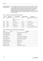
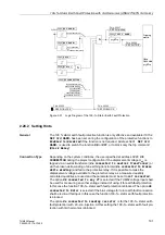
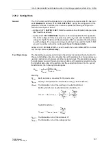
The sensitive earth fault detection is only effective and accessible if it has been set
during the configuration of the protective functions at address
=
with Iee1
or
with Iee2
. If one of the options with current evaluation was
selected during the configuration of the 90–%–stator earth fault protection (
, see Section 2.2) the sensitive current measuring input of the 7UM62 is
assigned to this feature. The user must be aware that the sensitive earth fault
detection possibly uses the same measuring input (I
EE2
) and thus the same
measuring quantity. If the sensitive earth fault detection is not required, this parameter
is set to
Disabled
. Address
is used to switch the function
ON
or
OFF
, or to block only the trip command (
Block Relay
).
Use as Rotor Earth
Fault Protection
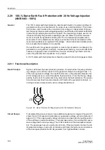
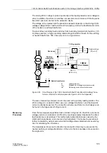
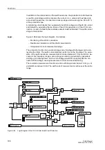
The highly sensitive earth current protection can be used to detects earth fault either
in the stator or in the rotor winding of the machine. A precondition is that the magnitude
of the measured current is a sufficient criterion. When the protected winding is isolated
or high-resistance earthed, sufficient magnitude of the earth current must be
produced. When, for example, used as rotor earth fault protection, a system frequency
bias voltage (U
V
≈
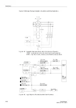
42 V must be applied to the rotor circuit by means of the 7XR61
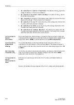
series device in Figure 2-88). In this case, the measured current is determined by the
magnitude of the bias voltage and the capacitance of the coupling capacitors of the
rotor circuit, which can be measured in order to ensure a closed measuring circuit
(address
). Approximately 2 mA is a typical pickup value. The monitoring
stage is ineffective is this value is set to 0. This can become necessary if the earth
capacitances are too small.
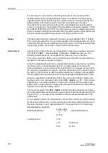
The earth current pick-up value
is chosen such that an earth resistance
R
E
between 3 k
Ω
and
5 k
Ω
is covered:
On the other hand, the setting value should correspond to at least twice the
interference current caused by the earth capacitances of the rotor circuit.
The
trip stage should be dimensioned for a fault resistance of about
1.5 k
Ω.
with Z
coup
- Impedance amount of the series device with nominal frequency
The
and
tripping time delays do not include the
operating times.
Use as Stator Earth
Fault Protection
Please also refer to section 2.26. For use as stator earth fault protection, a sufficient
current must be produced by an earthing transformer, if necessary. Instructions for the
dimensioning of the earth current transformer and the loading resistor are contained
in the pamphlet “Planning Machine Protection Systems”, Order No. E50400-U0089-
U412-A1-7600.
IEE>
U
V
R
E
-------
42 V
4 k
Ω
------------
10 mA
≈
≈
≈
Warning stage setting value e.g.:
IEE>>
U
V
R
E
Z
coup
+
-----------------------------
42 V
1.5 k
Ω
0.4 k
Ω
+
------------------------------------------
23 mA
≈
≈
≈
Trip stage setting value e.g.:

