Measured Value Monitoring Functions
245
7UM62 Manual
C53000-G1176-C149-3
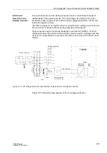
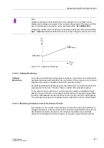
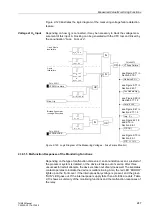
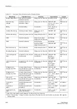
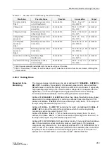
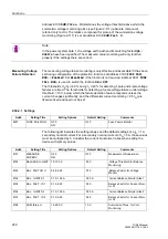
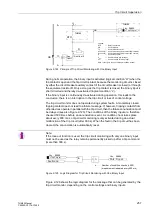
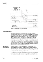
Figure 2-119 Voltage Symmetry Monitoring
Current and
Voltage Phase
Sequence
To detect swapped phase connections in the voltage and current input circuits, the
phase sequence of the phase-to-phase measured voltages and the phase currents
are checked by the monitoring.
Direction measurement with cross-polarized voltages, path selection for impedance
protection, and unbalance load detection all assume a clockwise phase sequence.
The current rotation is checked and reported individually for side 1 and side 2.
The phase sequence of the phase-to-ground voltages is verified by ensuring the
following
U
L1
leads U
L2
leads U
L3
Likewise, the phase sequence of the phase currents is verified by ensuring the
following:
I
L1
leads
I
L2
leads
I
L3
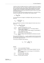
Verification of the voltage rotation occurs when each measured voltage is at least
|U
L1
|, |U
L2
|, |U
L3
| > 40 V/
√
3
Verification of the current rotation occurs when each measured current is at least
|
I
L1
|, |
I
L2
|, |
I
L3
| > 0.5 I
N
.
For counter-clockwise phase sequence, the annunciations ”
(FNo.
176
) or ”
”, (FNo.
) are output for side 1, or
”
”, (FNo.
) for side 2, as well as an OR link for these
annunciations ”
”, (FN.
For applications where the phase rotation of the measured quantities is counter-
clockwise phase in normal operation, this must be set in the device with the parameter
or an appropriately masked binary input. If the phase sequence
is changed in the relay, phases ‘L2’ and ‘L3’ internal to the relay are reversed, and the
positive and negative sequence currents are thereby exchanged (see also Section
2.43). The phase- related messages, malfunction values, and measured values are
not affected by this.
2.38.1.4 Fuse Failure Monitoring
In case of a measuring voltage failure caused by a short circuit or a phase failure in
the voltage transformer secondary system, a zero voltage can be simulated to
individual measuring loops. The measuring results of the undervoltage protection, the
impedance protection and other voltage-dependent protective functions may be
falsified in this way, which may cause an unwanted operation.
U
min
V
BALANCE I LIMIT
Slope:
BAL. FACTOR U
U
max
V

