Rotor Earth Fault Protection R, fn (ANSI 64R)
203
7UM62 Manual
C53000-G1176-C149-3
2.30.2 Setting Hints
General
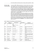
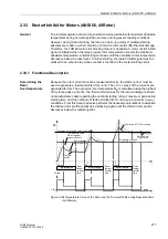
The rotor earth fault protection is only effective and accessible if it has been set during
the configuration of the protective functions at address
=
Enabled
.
Set
if the function is not required. Address
is used to
switch the function
or
OFF
, or to block only the trip command (
Also, configuration parameter
must be set to
. If it is not, a voltage U
RE
= 0 is displayed and evaluated,
so that the protection remains blocked.
Pick-Up Values
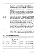
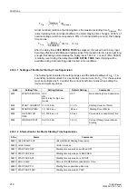
Since the protection calculates the ohmic rotor-earth resistance from the values
caused by the applied bias voltage, the thresholds for the warning stage
(
) and for the trip stage (
) can be set directly as
resistance values. The default settings are sufficient for the majority of cases. These
values can be changed depending on the insulation resistance and the coolant. Care
must be taken to allow a sufficient margin between the setting value and the actual
insulation resistance.
Delays
The time delay for the warning stage
is usually set to
approximately 10 s, and the delay for the trip stage
to
approximately 0.5 s. The set times are additional time delays not including the
operating times (measuring time, drop-out time) of the protective function.
Data for the
Coupling to the
Rotor Circuit
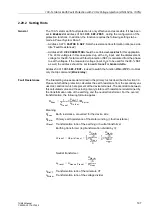
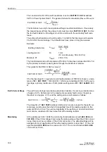
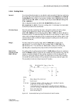
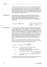
The setting of the coupling reactance
and the series resistance
enable the protection to calculate the earth resistance R
E
from the
complex equivalent diagram of the coupling capacitance of the coupling unit, the
series (e.g. measuring brush) resistance, the capacitance to earth of the excitation
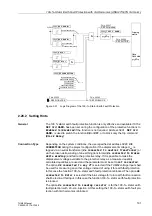
circuit, and the earth resistance of the excitation circuit; please refer to Figure 2-95.
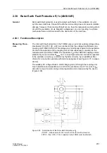
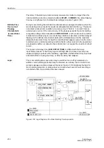
The equivalent circuit according to Figure 2-97 applies.
.
Figure 2-97
Equivalent Measuring Circuit for Rotor Earth Fault Protection
where
U
RE
Bias voltage of the rotor circuit
I
RE
Earth current
X
COUPLING
Total series reactance of the coupling circuit, consisting of coupling
capacitance and inductance (if applicable)
R
v
Total resistance of the coupling circuit, consisting of brush resistance,
protection resistance (if applicable) and damping resistance (if applicable)
C
E
Rotor earth capacitance
R
E
Rotor earth resistance
∼
I
RE
U
RE
X
COUPLING
R
V
= R
series
+ R
pre
+ R
z
C
E
R
E

