Functions
80
7UM62 Manual
C53000-G1176-C149-3
The higher voltage side has a wye connection and the lower voltage side a delta
connection. The phase rotation is n
⋅
30° (i.e. 5
⋅
30° = 150°). Side 1 (higher voltage
side) is the reference system. The vector group correction feature transforms the
currents flowing from side 2 to side 1.
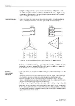
Isolated Starpoint
Figure 2-33 shows the vector group, the vector diagram for symmetrically flowing
currents and the transformation rules for a system with an isolated starpoint.
Figure 2-33
Vector Group Matching for a Y(N) d5 Transformer (Isolated Starpoint)
Deducting on side 2 the currents
I
L3
–
I
L1
results in the current
I
A
, which has the same
direction as
I
A
on side 1. Multiplying it with 1/
√
3 matches the absolute values. The
matrix describes the conversion for all three phases.
Earthed
Transformer
Starpoint
Figure 2-34 shows an example of a YNd5 vector group with earthed starpoint on the
Y-side.
The zero sequence currents are eliminated in this case. In Figure 2-34 on the right
side, the zero sequence currents are automatically eliminated by the current
difference formation, just as in the transformer there can be no zero sequence
currents outside the delta winding. On the left-hand side, the elimination of the zero
sequence current results from the matrix equation, e.g.
1
/
3
· (2
I
L1
– 1
I
L2
– 1
I
L3
) =
1
/
3
· (3
I
L1
–
I
L1
–
I
L2
–
I
L3
) =
1
/
3
· (3
I
L1
– 3
I
0
) = (
I
L1
–
I
0
).
Because of the zero sequence current elimination, fault currents which flow through
the CTs during earth faults in the network if there is an earthing point in the protected
zone (transformer starpoint or starpoint earthing transformer) are neutralized without
any special measures from outside.
I
A
I
B
I
C
1
1 0 0
0 1 0
0 0 1
I
L1
I
L2
I
L3
⋅
⋅
=
I
A
I
B
I
C
1
3
-------
1
–
0
1
1
1
–
0
0
1
1
–
I
L1
I
L2
I
L3
⋅
⋅
=
L
1
L
2
L
3
L
1
L
2
L
3
Side 1
Side 2
I
L1
I
L2
I
L3
I
A
√
3
⋅
I
A
I
L1
I
L2
I
L3


