Differential Protection (ANSI 87G/87M/87T)
93
7UM62 Manual
C53000-G1176-C149-3
Cross-Blocking
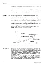
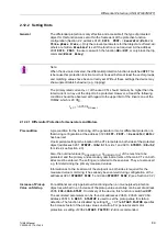
The inrush restraint can be extended by the so-called ”cross-block” function. This
means that not only the phase with inrush current exhibiting harmonics content in
excess of the permissible value is stabilized but also the other phases of the
differential stage IDIFF> are blocked. The duration for which the cross-block function
is operative after the differential current threshold has been exceeded is set at address
. Setting is in multiples of one cycle. Setting to
0
means
that the protection can initiate a tripping when the transformer is switched onto a
single-phase fault, even if an inrush current is flowing in another phase. When set to
∞
, the cross-block function is always effective. The duration of the blocking is specified
during commissioning. The default setting of 3 cycles has proven to be a good value.
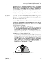
Besides the second harmonic, the 7UM62 can provide restraint with a further
harmonic. Address
is used to disable this harmonics
restraint, or to select the harmonic for it. The 3rd or the 5th harmonic are available.
Steady-state overexcitation of the transformer is characterized by odd harmonics
content. The third or fifth harmonic is suitable to provide stabilization. As the third
harmonic is often eliminated in transformers (e.g. in a delta winding), the fifth harmonic
is more commonly used.
Converter transformers also produce a content of odd harmonics which is practically
absent in the case of internal short-circuits.
The harmonic content which blocks the differential protection is set at address
. For example, if the 5th harmonic stabilization is used to avoid trip
during overexcitation, 30 % (default setting) are convenient.
Nth harmonic restraint operates individually per phase. However, it is also possible –
as it is for the inrush restraint – to set the protection such that not only the phase with
harmonics content in excess of the permissible value is stabilized but also the other
phases of the differential stage > are blocked (”cross-block” function). The duration for
which the cross-block function is operative after the differential current threshold has
been exceeded is set at address
. Setting is in multiples of
one cycle. Setting to
0
(default setting) means that the protection can initiate a tripping
when the transformer is switched onto a single-phase fault, even if a high harmonics
content is present in another phase. When set to
∞
, the cross-block function is always
effective.
If the differential current exceeds a multiple of the rated transformer current stated at
address
, no nth harmonic restraint takes place.
Tripping
Characteristic
The parameters of the tripping characteristic are set at addresses
to
.
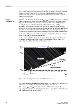
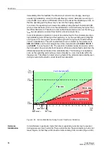
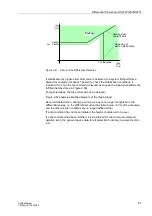
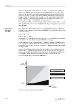
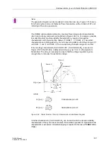
Figure 2-44 illustrates the meaning of the different parameters. The numerical values
at the branches are the parameter addresses.
Address
is the pickup value for the differential current. This is the total
fault current, regardless of the way it is divided between the windings of the protected
transformer. The pickup value is referred to the rated current corresponding to the
rated apparent power. For transformers, the setting should be between
0.2
and
0.4
.
It should be checked during commissioning that the selected pickup value is at least
twice the maximum differential current present in steady-state operation.
In addition to the pickup threshold
, the differential current is subjected to a
second pickup threshold. If this threshold (
) is exceeded, tripping is
initiated regardless of the magnitude of the restraint current (unstabilized high-speed
trip stage). This stage must be set higher than the
stage. As a guide: above
1/u
sc
of the transformer.
The tripping characteristic forms two more branches (Figure 2-44). Address
determines the slope of the first branch, whose starting point is specified in

