Inverse-Time Undervoltage Protection (ANSI 27)
165
7UM62 Manual
C53000-G1176-C149-3
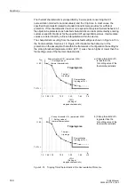
The pickup/dropout ratio is 101 % or 0.5 V absolute of the threshold set at address
. The integral action of the tripping time determination is “frozen“
between the pickup and the dropout value.
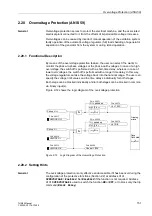
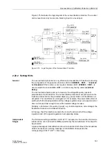
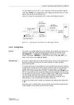
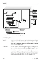
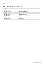
Figure 2-77 shows the logic diagram of the inverse undervoltage protection.
Figure 2-77
Logic Diagram of the Inverse-Time Undervoltage Protection
2.23.2 Setting Hints
General
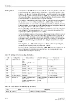
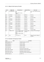
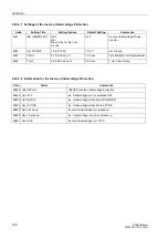
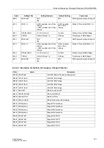
The inverse overvoltage protection is only effective and accessible if it has been set
during the configuration of the protective functions (Section 2.2, address
=
Enabled
). Set
Disabled
if the function is not required.
Address
is used to switch the function
ON
or
OFF
, or to
block only the trip command (
Block Relay
).
Setting Values
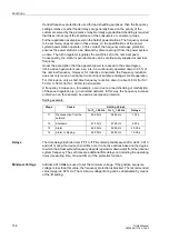
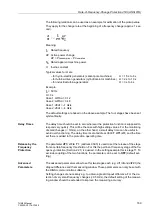
It must be considered that the positive phase-sequence system of the voltages and
thus also the pickup thresholds are evaluated as phase-to-phase quantities
(terminal voltage
⋅ √
3).
For the pickup values no hard and fast rules can be laid down. But since the protection
is used mainly to protect consumers (induction machines) from the consequences of
voltage drops, and to prevent loss of stability, the pickup value is normally set to
approx. 75 % of the nominal machine voltage, i.e. address
is set
to 75 V. In exceptional cases, where the voltage drop during startup is too big, it may
be necessary to set lower values. The time multiplier
must be selected
such that voltage drops that would lead to unstable operation are reliably
disconnected. On the other hand, the time delay must be big enough to avoid
disconnections in case of permissible short-time voltage dips.
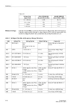
If required, the tripping time can also be extended by an additional time stage
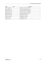
All setting times are additional time delays which do not include the operating times
(measuring time, drop-out time) of the protective function.
FNo. 06526
FNo. 06527
Up< TRIP
Tripping
matrix
FNo. 06523
FNo. 06520
&
Fuse Failure Monitor
U
1
FNo. 06525
U
T
TMin
TRIP CMD

