


3.3 Commissioning
349
7UM62 Manual
C53000-G1176-C149-3
3.3.3
Checking the Binary Inputs and Outputs
Preliminary Notes
The binary inputs, outputs, and LEDs of a SIPROTEC
®
4 device can be individually
and precisely controlled in DIGSI
®
4. This feature can be used, for example, to verify
control wiring from the device to substation equipment (operational checks), during
commissioning. This test feature shall not be used while the device is in service on a
live system.
Note: After the Hardware Test is complete, the device enters a start-up phase. All
message buffers are erased. If necessary, the buffer contents can be read out and
saved using DIGSI
®
4.
The interface test can be done using DIGSI
®
4 in the online operating mode:
G
Open the
Online
directory by double-clicking; the operating functions for the
device appear.
G
Click on
Test
; the function selection appears in the right half of the window.
G
Double-click in the list view on
Hardware Test
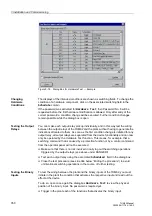
. The dialog box of the same name
opens (see Figure 3-18).
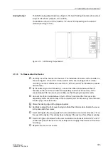
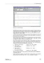
Hardware Test:
Dialog Box
The dialog box is horizontally divided into three groups:
BI
for binary inputs,
REL
for
output relays, and
LED
for light-emitting diodes. Each of these groups is associated
with an appropriately marked switching area. By clicking in an area, components
within the associated group can be turned on or off.
In the
Status
column, the present conditions of the hardware components are
symbolically shown. The present physical conditions of the binary inputs and output
relays are shown as symbols for open and closed contacts. The present condition of
a light-emitting diode is shown as the symbol for an LED, turned on or off.
The possible intended condition of a hardware component is indicated with clear text
under the
Schedule
column, which is next to the
Status
column. The intended
condition offered for a component is always the opposite of the present state.
The right-most column indicates the operating equipment, commands, or messages
that are configured (masked) to the hardware components.
DANGER!
Changing the status of a binary input or output using the test feature of DIGSI
®
4
results in an actual and immediate, corresponding change in the SIPROTEC
®
device. Connected equipment such as circuit breakers will be operated by these
actions!


