Functions
196
7UM62 Manual
C53000-G1176-C149-3
In addition to the determination of the earth resistance, the protection function features
an earth current stage which processes the current r.m.s. value and thus takes into
account all frequencies. It is used as a backup stage and covers approx. 80 to 90 %
of the protection zone.
A monitoring circuit checks the coupled external 20 Hz voltage and the 20 Hz current
and detects by evaluating them a failure of the 20 Hz generator or of the 20 Hz con-
nection. In case of a failure, the resistance determination is blocked. The earth current
stage remains active.
Logic
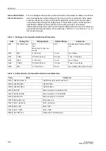
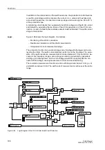
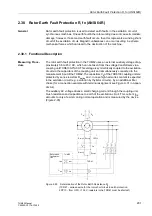
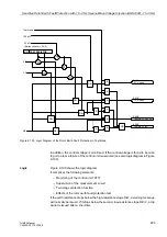
Figure 2-94 shows the logic diagram. It comprises:
−
Monitoring of the 20 Hz connection
−
Resistance calculation and threshold value decision
−
Independent current measurement stage
The protection function has an alarm stage and a trip stage. Both stages can be de-
layed with a timer. The earth current detection acts only on the trip stage. The evalu-
ation of the earth resistance measurement is blocked between 10 Hz and 40 Hz, be-
cause in this frequency range a zero voltage can also be generated by generators
starting up or slowing down. Such a zero voltage would then superimpose the con-
nected 20 Hz voltage, causing measurement errors and overfunctioning.
The resistance measurement function is active with frequencies below 10 Hz (i.e. at
standstill) and above 40 Hz. The earth current measurement is active over the entire
range.
Figure 2-94
Logic Diagram of the 100-% Stator Earth Fault Protection
>U20 failure
5476
5307 U20 MIN
5308 I20 MIN
5302 R< SEF ALARM
5303 R<< SEF TRIP
5306 SEF I>>
>S/E/F BLOCK
5173
5304 T SEF ALARM
5487
SEF100 Alarm
5488
SEF100 PICKUP
5305 T SEF TRIP
5489
SEF100 TRIP
5482
SEF100 BLOCKED
U
20
I
20
R
Num.
filter
U
SEF
I
SEF
U
20
I
20
&
&
&
&
&
OR
0,5 s
OR
&
OR
f > 10 Hz
and
f
≤
40 Hz
5486
Failure SEF
Tripping
matrix
Tmin TRIP
CMD
&

