Functions
144
7UM62 Manual
C53000-G1176-C149-3
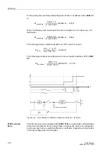
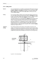
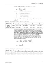
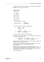
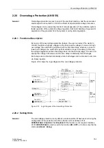
The setting Z
a
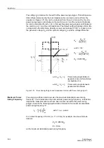
is decisive for the width of the power swing polygon. This setting value
Za is determined by the total impedance Z
tot
and can be derived from the
equation in Figure 2-70. Z
tot
can be calculated from the sum of Z
b
and Z
d
; then the
power swing angle is valid between the machine e.m.f. and the network. Optionally,
Z
tot
can be calculated from Z
b
+ Z
c
; in this case the power swing angle is valid between
the machine e.m.f. and the unit transformer. The default setting of address
corresponds to the latter case. Usually, a power swing angle
δ
= 120° is chosen, since
the generator voltage U
G
and the system voltage U
N
equal the voltage difference:
Figure 2-70
Power Swing Polygon and Impedance Vectors with Power Swing Angle
δ
Maximum Power
Swing Frequency
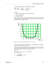
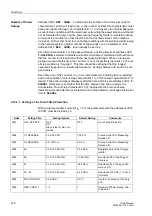
The polygon width Z
a
determines also the maximum detectable power swing
frequency. The consideration that, at maximum power swing frequency, at least two
impedance measurements must have been carried out within the power swing
polygon, leads to the following approximative formula for the maximum detectable
power swing frequency f
P
:
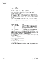
For a rated frequency of 50 Hz (i.e. T = 20 ms), for example, the above formula
delivers:
as the maximum detectable power swing frequency.
Z
a
Z
tot
2
⁄
δ
2
⁄
(
)
tan
------------------------
=
Z
a
Z
tot
2
⁄
120° 2
⁄
(
)
tan
---------------------------------
=
Z
a
0.289 Z
tot
⋅
≈
with
δ
= 120°
with Z
tot
= Z
b
+ Z
c
Power swing angle between
generator and unit transformer
(as illustrated) or
with Z
tot
= Z
b
+ Z
c
Power swing angle between
generator and network
Z
c
Z
b
Z
a
Z
d
Re(Z
)
Im(Z)
í
ì
î
ì
î
í
Z
b
+
Z
c
Z
b
+
Z
d
δ
U
N
U
G
---------
1
=
Z = R + jX
f
P
4
π
---
1
T
---
Z
a
Z
tot
---------
⋅ ⋅
=
with T = a.c. period
Z
a
0.289 Z
tot
⋅
≈
f
P
18 Hz
≈

