Functions
198
7UM62 Manual
C53000-G1176-C149-3
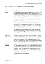
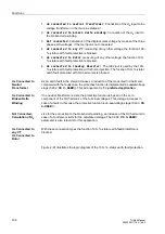
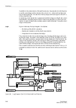
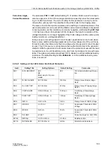
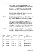
The conversion factor of the earth resistance is set as
at address
in Power System Data 1. The general formula for calculation (R
Eprim
/ R
Esec
) is:
This formula is true only for nearly ideal earthing or neutral transformers. If necessary,
the measuring result from the primary tests must be set as
. For this
the fed fault resistance (trip stage) is put into relation with the secondary fault resis-
tance.
The primary fault resistance should be set to 1 to 2 k
Ω
for the trip stage and to approx.
3 to 8 k
Ω
for the alarm stage. The default times have proven to be good values.
Example:
Loading resistor
R
L
10
Ω
(10 A continuously, 50 A for 20 s)
Miniature CT
ü
MinCT
200 A / 5 A
The transformation ratio of the miniature CT 400 A:5 A has been reduced to 200 A:5 A
by the primary conductor passing twice through the transformer window.
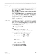
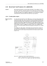
This yields for FACTOR R SEF a value of:
If for the trip stage R<< a generator-side fault resistance of 1000
Ω
is chosen, a resis-
tance of
= 1000
Ω
/8.33 = 120
Ω
is set at address
. For the warn-
ing stage, a primary resistance of 3 k
Ω
yields a setting value of
= 360
Ω
.
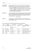
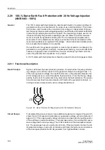
Earth Current Stage
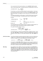
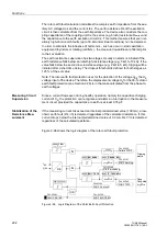
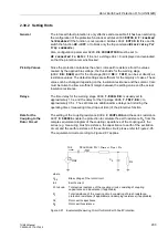
The earth current stage has a backup protection function. It is set to a protected zone
of approx. 80 %. Referenced to the maximum secondary fault current, the pickup
threshold is at approx. 20 %, and the setting value is calculated as follows:
The delay time
(address
), which is also relevant for the earth cur-
rent stage, must be less than the 50 A capability time of the loading resistor (in this
example 50 A for 20 s). The overload capability of the earthing or neutral transformer
must also be considered if it lies below that of the loading resistor.
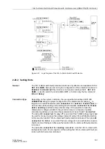
Monitoring
At the addresses
the monitoring thresholds are set with
and
. If the 20 Hz voltage drops below the pickup value without the 20 Hz current
rising, there must be a problem of the 20 Hz connection. The default settings will be
adequate for most applications. Where the loading resistor is less than 1
Ω
, the volt-
age threshold
must be reduced to 0.5 V. The current threshold
can be left at 10 mA.
FACTOR R SEF
ü
Transf
2
ü
Divider
ü
MinCT
--------------------
⋅
=
10kV
3
--------------
500V
3
--------------
⁄
Earthing transformer
ü
Transf
FACTOR R SEF
10 000 V
3
------------------------
3
500 V
----------------
⋅
è
ø
æ
ö
2
9
-----------------------------------------------------
500 200
⁄
200 5
⁄
------------------------
8.33
=
⋅
=
SEF100 I>>
0.2
U
Nsec
R
L
----------------
1
ü
MinCT
-------------------
0.2
500 V
10
Ω
----------------
5 A
200 A
----------------
⋅
⋅
0.25 A
=
=
⋅
⋅
=


