


A Appendix
482
7UM62 Manual
C53000-G1176-C149-3
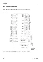
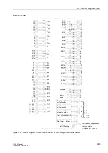
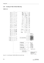
A.2
General Diagrams (IEC)
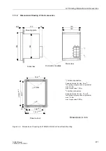
A.2.1
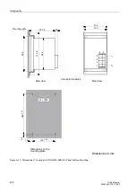
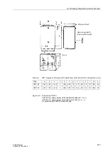
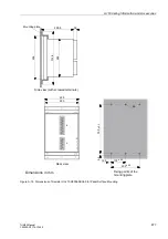
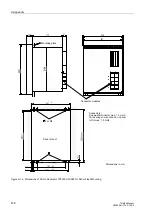
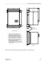
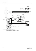
Housing for Panel Flush Mounting or Cubicle Installation
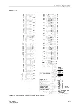
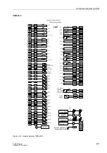
7UM621
∗
–
∗
D/E
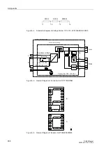
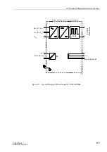
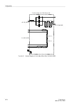
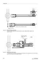
Figure A-20 General Diagram 7UM621
∗
−
∗
D/E (Panel Flush Mounting or Cubicle Installation)
Power-
Earthing at Side
supply
Wall of Housing
F1
F2
( )
~
+
-
Life status
F4
F3
contact
1 2
3 2
Interference suppression
capacitors at the
relay contacts,
Q1
Q2
I
L1S2
Q3
Q4
I
L2S2
Q5
Q6
I
L3S2
R13
R14
U
E
R15
R17
U
L1
R18
U
L2
R16
U
L3
F5
F6
BI1
F8
F9
F10
F7
BI2
BI4
BI5
BI3
K9
K10
BI6
K11
K12
BI7
R3
R4
BO3
R6
BO4
R5
BO5
R2
BO2
R1
BO1
R8
R7
1 2
3 2
BO6
R9
R10
BO7
R11
R12
BO8
K6
K5
1 2
3 2
BO11
Q7
Q8
I
EE2
System interface
or analog output
B
A
Front oper. interface
Time Synchronization
Service Port
C
Analog output
D
F
o
r
th
e
p
in
a
ss
ig
nm
ent
of
Inte
rfac
es
,
re
fer
to
T
a
b
le
to
in
Su
bs
ec-
ti
on
3.2
.1
J1
J2
I
L1S1
J3
J4
I
L2S1
J5
J6
I
L3S1
J7
J8
I
EE1
K1
K2
BO9
K3
K4
BO10
K8
K7
1 2
3 2
BO12
K13
K14
TD1
K15
K16
TD2
(+)
(–)
(+)
(–)
K17
K18
TD3
(+)
(–)
Ceramic, 4.7 nF, 250 V
or Thermobox
or Thermobox


