3 Installation and Commissioning
338
7UM62 Manual
C53000-G1176-C149-3
Time
Synchronization
Interface
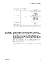
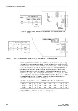
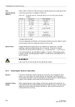
Either 5 VDC, 12 VDC or 24 VDC time synchronization signals can be processed if the
connections are made as indicated in Table 3-22
.
*) assigned but not used
For the pin assignment of the time synchronization interface in panel surface-mounted
devices, please refer to the Appendix (Figures A-22 to A-25).
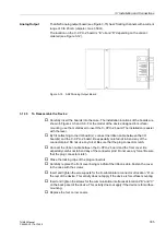
Optical Fibers
Signals transmitted via optical fibers are unaffected by interference. The fibers
guarantee electrical isolation between the connections. Transmit and receive
connections are shown with the symbols
for transmit and
for receive.
The normal setting for the optical fiber interface is ”Light off.” If this setting is to be
changed, use the operating program DIGSI
®
4, as described in the SIPROTEC
®
4–
System Manual.
3.2.2
Checking the Device Connections
General
The device connections must be checked to ensure the correct integration of the
device e.g. in the cubicle. The check includes, among others, the wiring and the
functionality as specified in the set of drawings, the visual inspection of the protection
system and a simplified functional test of the protective device.
Auxiliary Voltage
Supply
Before applying power supply voltage or measuring quantities for the first time, be
sure the device has been in the operating area for at least two hours. This time period
allows the device to attain temperature equilibrium, and prevents dampness and
condensation from occurring.
Table 3-22
Pin Assignments for the D-Subminiature Port of the Time Synchronization
Interface
Pin No.
Designation
Signal Meaning
1
P24_TSIG
Input 24 V
2
P5_TSIG
Input 5 V
3
M_TSIG
Return Line
4
–*)
–*)
5
Screen
Screen Potential
6
–
–
7
P12_TSIG
Input 12 V
8
P_TSYNC*)
Input 24 V*)
9
Screen
Screen Potential
WARNING!
Laser rays! Do not look directly into the optical fiber cables!


