Differential Protection (ANSI 87G/87M/87T)
91
7UM62 Manual
C53000-G1176-C149-3
Add-on
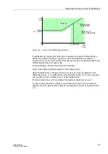
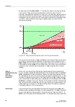
Stabilization During
Current Trans-
former Saturation
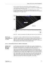
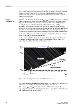
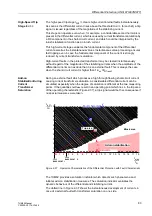
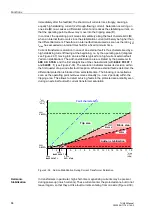
Where very high currents flow through the protected object during external short-
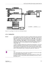
circuits, an add-on stabilization takes effect that is set at address
(stabilization in case of saturation). Please note that the stabilizing current is
the arithmetical sum of the currents entering and leaving the protected zone, i.e. that
it is twice the actually flowing current. The default setting of
4.00 I/InO
should be
kept. The maximum duration of the add-on stabilization is set at address
ADD ON-STAB. in multiples of one period. This time is the maximum duration of the
blocking after leaving the add-on stabilization area in case of high-current external
faults. The setting depends, for instance, on the disconnecting time of the upstream
protection. The default setting
15 *1P
is a good value.
Time Delays
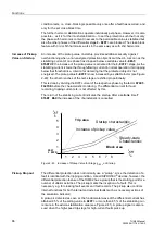
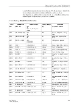
In special cases it may be advantageous to delay the trip signal of the differential
protection with an additional time stage. The timer is started
is
started when an internal fault in the generator or the motor has been detected.
is the time delay of trip stage
I DIFF>>
. A separate time stage is
provided for each differential protection level and each phase. The dropout delay is
linked to the minimum trip command duration that is valid for all protection functions.
All setting times are additional time delays which do not include the operating times
(measuring time, drop-out time) of the protective function.
2.12.2.2 Differential Protection for Transformers
Precondition
A precondition for the operation of the transformer differential protection is that during
configuration address
0120
was set to =
Three-phase transf.
.
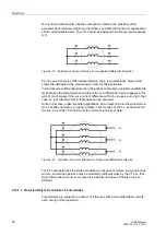
To ensure the correct polarity for the formation of the differential current, the polarity
of the sets of CTs must be specified. This has been done during the configuration,
when entering the location of the starpoints of the sets of CTs on both sides of the
transformer at addresses
for side 1 and
for side 2, see Section 2.3).
Also, the nominal data (S
N TRANSF
, U
N WIND S1
, U
N WIND S2
) of both sides of the
transformer, as well as the primary and secondary rated currents of the main CTs on
both sides were requested. The settings are referred to these values. They are also
used e.g. for determining the primary measured values.
Information as to the treatment of the starpoint on both sides is required for the
elimination of the zero sequence current and for the measured value monitoring
(summation current monitoring); it has already been entered during configuration at
the
0241
and
0244
(see Section 2.3.2).
Matching of
Absolute Values
and Vector Group
Matching
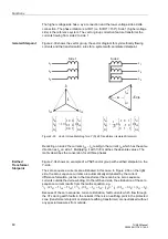
When used as transformer protection, the 7UM62 automatically computes from the
rated data of the protected transformer the current-matching formulae which are
required to match the vector group and the different rated winding currents. The
currents are converted such that the sensitivity of the protection always refers to the
power rating of the transformer. Therefore, no circuitry is required for matching of the
vector group and no manual calculations for converting of rated currents are normally
necessary.
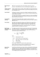
The unit requires the following data for each winding
−
MVA rating (apparent power) S
N
in MVA (see above),
−
Rated voltage U
N
in kV (see above)
−
Vector group numeral

