152
6.3. Speed control mode
Speed control mode is suitable for precise speed control applications, such as and CNC
machines, drilling machine, etc. There are two types of command sources: (1) analog input,
(2)
internal register.
The analog command controls the motor speed by external voltage input.
The register input controls the speed in two methods.
The first method is to manually set the 7 different required speeds in the 7 command registers
(PC05~PC11) before starting the operation, and then switch DI of SP1, SP2, SP3 of CN1.
The second method is to changes the value in the register through communication software
with RS485 or USB.
To deal with the problem of non-continuous speed when switching registers, you can use the
S-curve function, thus the motor can keep running smoothly when switching to different speed.
In a closed-loop system, the servo drive uses gain adjustment and the accumulative integrated
PI controller. And it also provides two operation modes (manual and automatic).
In manual mode, you can set all the parameters, so all the auto or auxiliary functions are
disabled. In auto gain adjustment modes, the servo drive performs load inertia estimation and
provides parameter adjustment function. In this case, the parameter setting values are
regarded as the initial values. This simple mode provides a robust system function for the user,
which is different from the adaptability rule that requires a longer learning time in the automatic
operation mode. Simple operation mode can suppress external load interference and
mechanism resonance in real time, and tolerate load inertia change.
Analog
signal
Speed linear
voltage filter
(PC36)
Analog command
speed max output
(PC12)
Speed limit offset
(PC26)
S-type smoother
(PC01~PC03)
S-type smoother
(PC01~PC03)
Inner speed
command
(PC05~PC11)
SP1-SP3 signal
CN1
Control mode
option (PA01)
speed filter constant
(PB21)
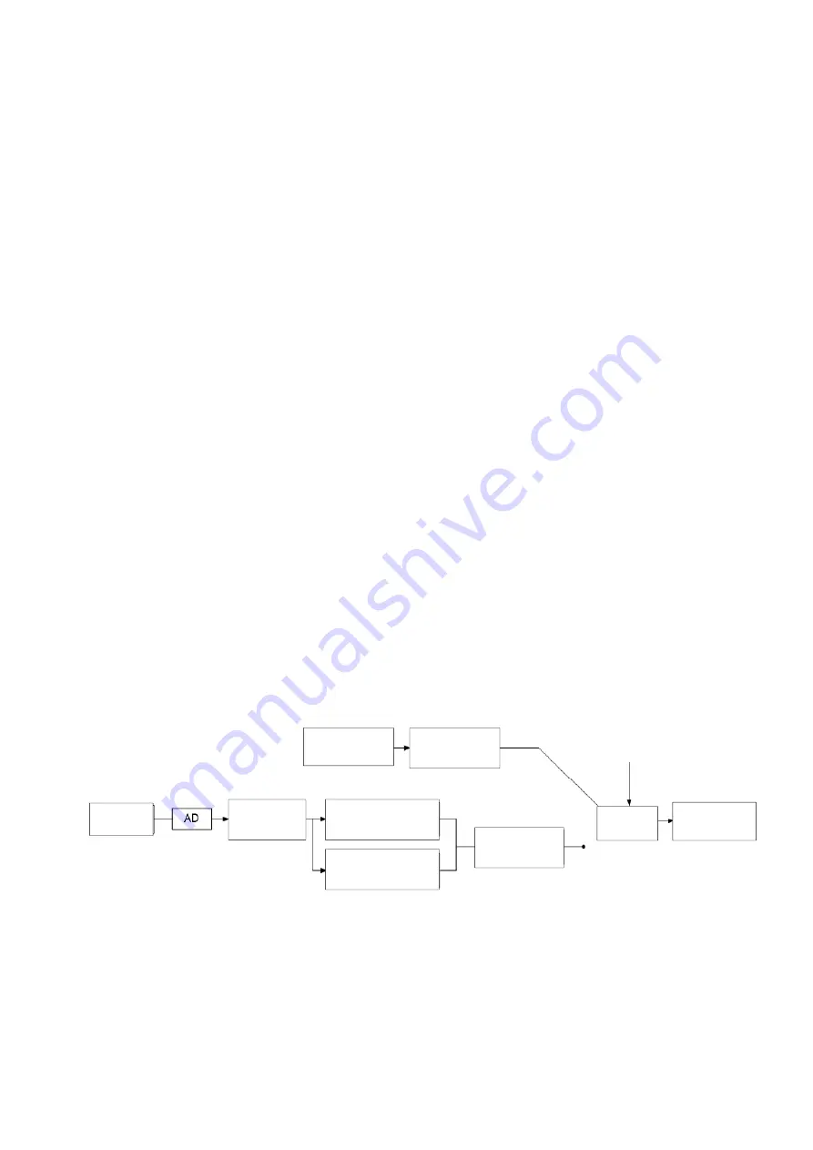
The upper part of the graph is the internal speed command, which controls the speed
command by manually input parameter and switches by terminal DI. The lower part of the
graph is the external analog input ±10V voltage. After processing by A/D, it calculates the set
analog command max output(scaling) and voltage offset value and then outputs to the next
part.
Summary of Contents for SDP Series
Page 33: ...20 400V series DC 24V Power supply Note terminal P N cannot be grounded ...
Page 45: ...32 4 The last step is to fasten the screw of housing ...
Page 385: ...372 ...
Page 405: ...392 ...
Page 499: ...486 SME L040 SME L075 SME L100 SME L150 ...
Page 500: ...487 SME L200 SME L300 SME M100 SME M150 ...
Page 509: ...496 When the load reaches 300 the operation time is 5 51 seconds ...
Page 555: ...542 14 5 Manual version and revision history Manual version V1 00 Release month July 2022 ...


