SD710 Series Servo Drive User Manual Chapter 5 Commissioning and Operation
26
Steps
Item
Operations
1
Power on electric
power
(a) The drive is powered up and "Off" is displayed on the panel.
2
Control mode
selection
Pn000.X = 0 (control mode selected as position mode).
Pn200 = 0 (the source of the pulse command is the CN1 terminal).
3
Selecting the pulse
form
Pn201 = 0 ("Quadrature AB" pulse input method)
Pn202.X=0 (pulse input is positive logic).
4
Setting the
electronic gear
ratio
Pn204 = 8388608 (23-bit encoder), Pn206 = 10000. (For every 10000 pulses
received by the driver, the motor runs 1 revolution)
5
Sending pulses to
the servo
The PLC sends pulses at a constant frequency, in a certain number of ways, and
at certain intervals.
6
Check the received
pulse frequency
and pulse count
Monitoring function code Un007 to determine whether the received pulse speed
matches the actual one sent.
Monitor Un006 and check that the input pulse counter Un006 matches the actual
number sent.
5.3 Speed (internal setting) mode
5.3.1 Summary of functions
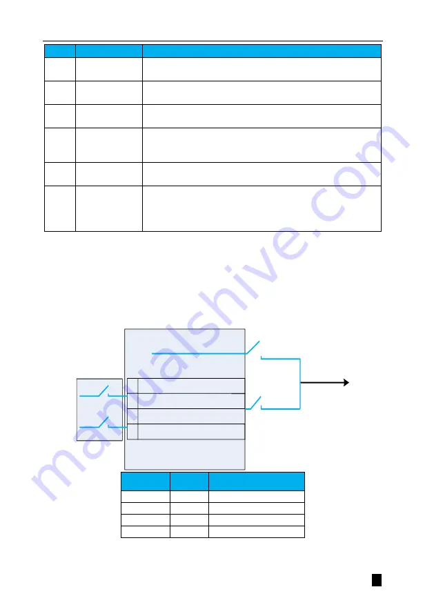
The speed command source supported by this product is mainly set by internal registers.
Internal register setting speed is a function that sets the motor speed in advance by the internal user parameters of the
Servo Drive and selects it using an external input signal for speed control operation without having to configure a speed
generator or pulse generator externally.
Internal number given
(Pn304)
Pn303.X = 0
Pn303.X=0: Internal number given (Pn304)
0
Pn303.Y=0: Internal number given (Pn305)
1
Pn303.Z=0: Internal number given (Pn306)
2
Pn303.W=0: Internal number given (Pn307)
3
SPDA
SPDB
Pn303.X = 4
In speed mode
speed command
source
Input terminal(
X)
SPDB
SPDA
Command Source
Selection
0
0
Pn303.X setting
0
1
Pn303.Y setting
1
0
Pn303.Z setting
1
1
Pn303.W setting
Figure 5.23 Block diagram of speed command source


