SD710 Series Servo Drive User Manual Chapter 3 Wiring and Installation
32
3.5.4 Braking Wiring
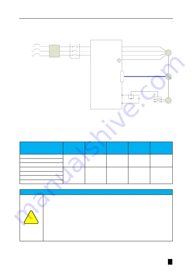
The wiring of the brake input signal has no polarity and requires the user to prepare 24 V voltage. An example of the
standard connection between the brake signal BK and the brake power supply is shown below.
(Brake power
supply)
Y+(BK+)
Y- (BK-)
Servo
system
U
V
W
L1
L2
L3
CN2
+24V
M
PG
BK
+24V
Brake control relay
BK-RY
Noise
filter
3 phase
220Vac
(
3 phase
)
Figure 3.19 Wiring diagram for brake
Holding brake wiring considerations.
The length of the motor holding cable must take full account of the voltage drop caused by the cable resistance, and the
braking operation must ensure that the input voltage is at least 21.6 V. The motor holding braking are shown in the table
below.
Table 3-15 Table of parameters of brake
Motor model
Maintaining
torque
(N. m)
Supply
voltage
(V) ± 10%
Release
time
(ms)
Attraction
time
(ms)
Rotary
clearance
(° )
VM7-L06A-R2030-
□2
1.5
24
<20
<50
<0.5
VM7-L06A-R4030-
□2
VM7-L06A-R6030-
□2
VM7-L08A-R7530-
□2L
4
24
<40
<60
<0.5
VM7-L08A-R7530-
□2
VM7-M08A-R7530-
□2L
VM7-M08A-R7530-
□2
Note
●
The holding brake coil has no polarity
●
Servo enable (S-ON) should be turned off after the servo motor is stopped.
●
The brake may click when the motor with the built-in brake is running, but there is no
functional effect.
●
When the holding coil is energized (holding brake open state), flux leakage may occur at the
shaft end, etc. Be careful when using instruments such as magnetic sensors near the motor.
●
The brake mechanism is a non-energy-activated fixed special mechanism that cannot be
used for dynamic braking purposes and is used only when the servo motor is held in a stopped
state.
!


