SD710 Series Servo Drive User Manual Chapter 5 Commissioning and Operation
25
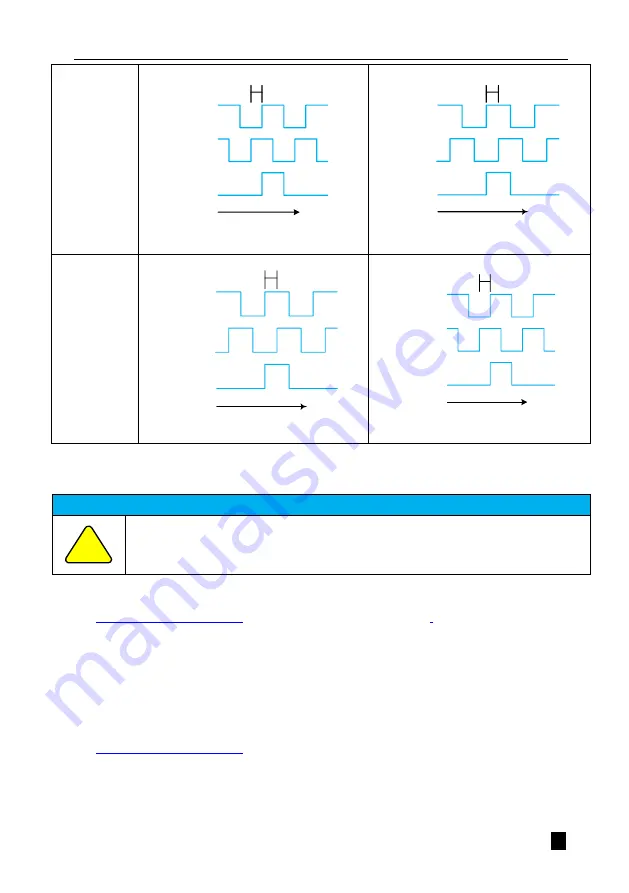
Pn002=0
90°
Time
B-ph ase
C-ph ase
A-ph ase
Phase A overtakes phase B
90°
A-ph as e
B-ph as e
C-ph as e
Time
Phase A lags behind phase B
Pn002=1
90°
A-phase
B-phase
C-phase
Time
Phase A lags behind phase B
90°
Time
A-phase
B-phase
C-phase
Phase A overtakes phase B
Figure 5.22 Effect of inverse pulse divider output pickup
The parameter Pn072 can be set to invert the AB-phase signal logic of the divided output pulse.
Precautions
●
The phase polarity of the AB phase pulses output by the crossover is related to the direction of rotation of
the motor, in addition to Pn072. When applying this function, adjust the direction of rotation of the motor
(Pn002) first, and then determine whether the polarity of the divider output pulse needs to be reversed.
(2) Crossover pulse output wiring
See
"Multi-function CN1 terminal wiring"
for details of the crossover pulse output wiring
5.2.12 Example of Position Control Operation
In position mode, there are two ways to receive pulses: one is a low-speed pulse interface and the other is a high-speed
pulse interface.
The general open collector pulse command frequency is 200kHz maximum, and the low speed pulse interface is
recommended; when the user uses higher frequency or specific linear output pulses, the linear differential input interface
is recommended.
See
"Multi-function CN1 terminal wiring"
for details of low-speed pulse and high-speed pulse wiring.
The operation of the servo drive position control is described using the linear differential input as an example.
Example
: PLC linear differential output pulses, pulse type is orthogonal AB, requires one rotation of the motor every
10,000 pulses, the operation steps are shown in Table 5-8.
Table 5-8 Example of external encoder commissioning using 5V differential output
!


