Chapter 3: Using the Web Interface
92
1
Configured power meters with basic details and
current readings for each phase .
See
Dashboard - Power Meters
(on page 92).
2
Enabled thresholds show alerts in red and
yellow.
See
Dashboard - Alerted Sensors
(on page 93)
3
Alarms that need attention.
See
Dashboard - Alarms
(on page 94).
4
Chart of recent data.
See
Dashboard - Power Meter History
(on
page 96).
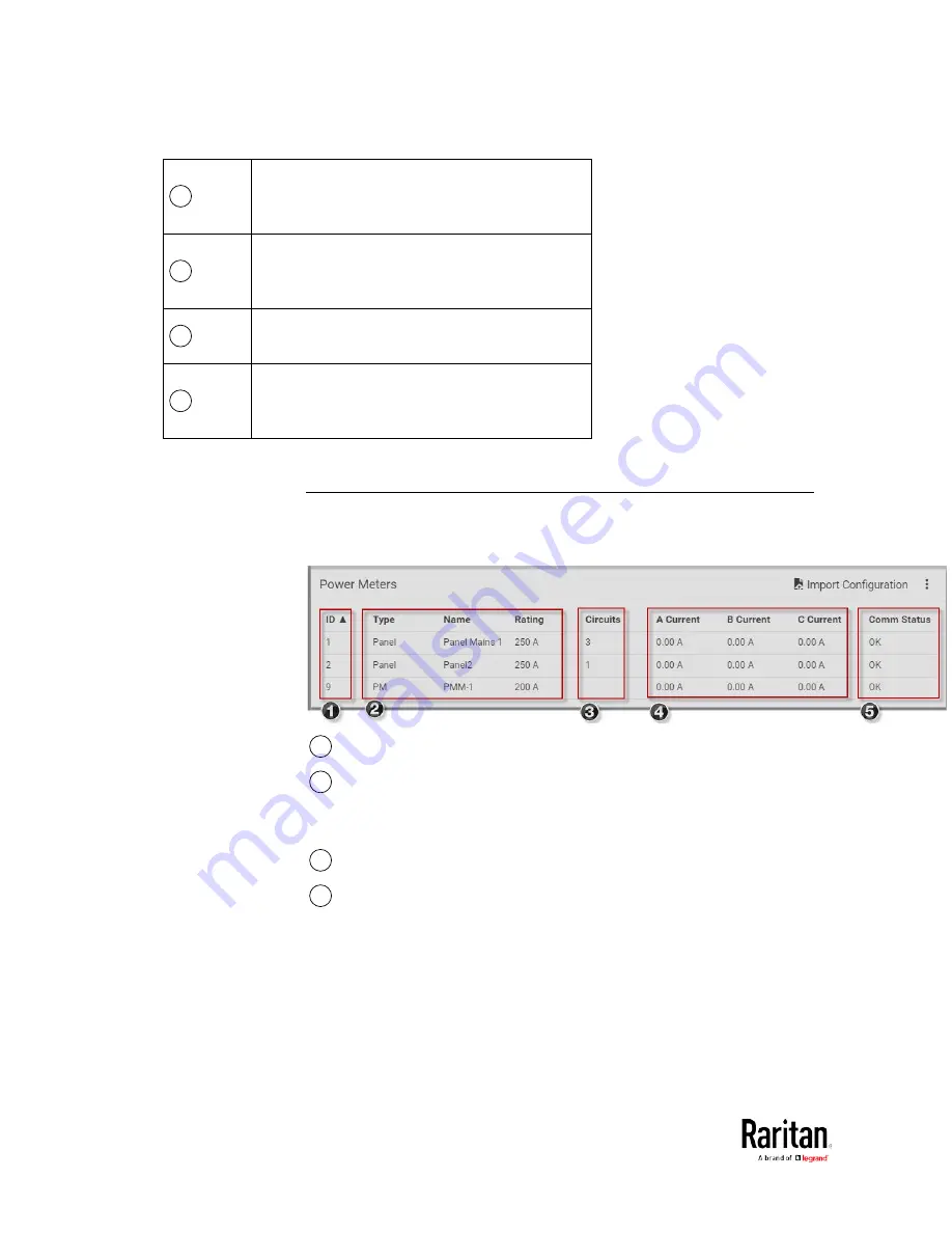
Dashboard - Power Meters
The Power Meters section of the Dashboard shows all configured power
meters and panels, with some details for each.
1
ID: The PMM rotary switch setting for the power meter.
2
Type: Panel or PM
Name: The configured name
Rating: The configured circuit rating.
3
Circuits: The number of configured circuits
4
A Current/B Current/C Current: The current reading in Amps for
each phase.
Содержание PMC-1000
Страница 3: ...BCM2 Series Power Meter Xerus Firmware v3 4 0 User Guide...
Страница 23: ...Chapter 1 Installation and Initial Configuration 11 Panel Wiring Example...
Страница 54: ...Chapter 1 Installation and Initial Configuration 42 Branch Circuit Details...
Страница 76: ...Chapter 2 Connecting External Equipment Optional 64...
Страница 123: ...Chapter 3 Using the Web Interface 111...
Страница 558: ...Appendix D RADIUS Configuration Illustration 546 Note If your BCM2 uses PAP then select PAP...
Страница 559: ...Appendix D RADIUS Configuration Illustration 547 10 Select Standard to the left of the dialog and then click Add...
Страница 560: ...Appendix D RADIUS Configuration Illustration 548 11 Select Filter Id from the list of attributes and click Add...
Страница 563: ...Appendix D RADIUS Configuration Illustration 551 14 The new attribute is added Click OK...
Страница 564: ...Appendix D RADIUS Configuration Illustration 552 15 Click Next to continue...
Страница 594: ...Appendix E Additional BCM2 Information 582...
Страница 612: ......


