


TC1784
FlexRay™ Protocol Controller (E-Ray)
User´s Manual
20-236
V1.1, 2011-05
E-Ray, V3.13
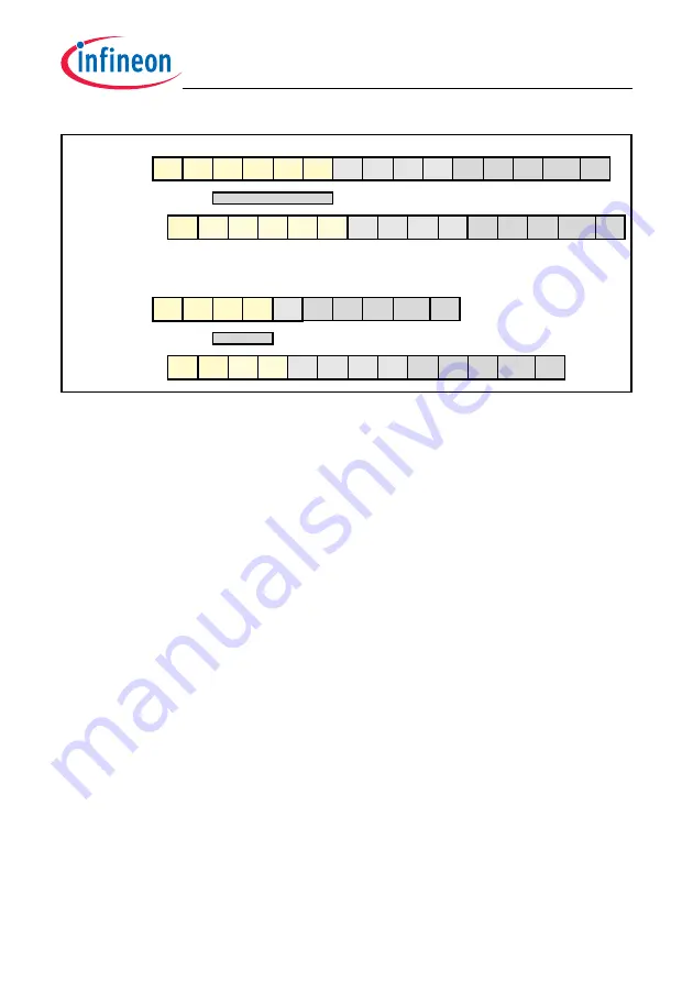
Figure 20-19 Delay start of IBF
⇒
MBF
The internal signal “disable_i2m” is always active when the TBF
⇒
MBF is in state “hs1-
rd”, “hs2-rd”, “hs3-rd” or “mbs-rd” and when the SS
⇒
MBF is in state “hs1-rd” or “mbs-
rd”.
The IBF
⇒
MBF is hold in state “start” until the internal signal “disable_i2m” gets
inactive.
These additional time-steps are independent of any address-counter-values. This
means, the IBF
⇒
MBF has to wait even if it writes to another buffer than the internal
transfer.
Multiple requests of transfers between IBF/OBF and Message RAM
The time required to transfer the contents of a Message Buffer between IBF / OBF and
Message RAM depends on the number of 4-byte words to be transferred, the number of
concurrent tasks to be managed by the Message Handler, and in special cases the type
and address range of the internal transfer. The number of 4-byte words varies from 4
(Header Section only) to 68 ( maximum Data Section) plus a short setup time
to start the first transfer, while the number of concurrent task varies from one to three.
The 4 Header words have to be included in calculation even if only the Data Section is
requested for transfer.
The following concurrent tasks are executed under control of the Message Handler:
•
Data transfer between IBF or OBF and MBF
•
Data transfer between TBF1 and MBF, search next TX / RX Message Buffer CHA
•
Data transfer between TBF2 and MBF, search next TX / RX Message Buffer CHB
Transfers between IBF and MBF respectively MBF and OBF can only be handled one
after another. In case that e.g. a IBF
⇒
MBF has been started shortly before a
dw127
start
start
start
start
start
start
start start
idle
idle
idle
idle
hs1-rd
hs1-rd
mbs-rd
hs2-rd hs3-rd
mbs
hs2
hs3
hs2
hs1
hs3 mbs dw1/2 dw3/4 dw5/6
...
IBF=>MBF
hs1 hs2
mbs
TBF=>MBF
start
hs1
hs3 mbs
disable_i2m
SS=>MBF
start
mbs-rd
IBF=>MBF
disable_i2m
dw127
dw1/2 dw3/4 dw5/6
...
dw127
dw1/2 dw3/4 dw5/6
...
dw127
dw1/2 dw3/4 dw5/6
...
Summary of Contents for TC1784
Page 1: ...User s Manual V1 1 2011 05 Microcontrollers TC1784 32 Bit Single Chip Microcontroller ...
Page 3: ...User s Manual V1 1 2011 05 Microcontrollers TC1784 32 Bit Single Chip Microcontroller ...
Page 950: ...TC1784 Direct Memory Access Controller DMA User s Manual 11 132 V1 1 2011 05 DMA V3 03 ...
Page 1949: ...TC1784 General Purpose Timer Array GPTA v5 User s Manual 21 297 V1 1 2011 05 GPTA v5 V1 14 ...
Page 2350: ...w w w i n f i n e o n c o m Published by Infineon Technologies AG Doc_Number ...


