Goodrive350-19 series VFD Optional peripheral accessories
-507-
Image
Name
Description
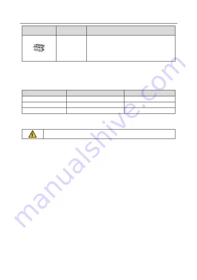
Output reactor
Accessory used to lengthen the valid transmission
distance of the VFD, which effectively restrict the
transient high voltage generated during the switch-on
and switch-off of the IGBT module of the VFD.
D.3 LCD keypad
You can configure the LCD keypad and LCD keypad installation bracket (which are optional parts) for
the VFD.
Item
Model
Oder No.
LCD keypad
KEY-LCD01-ZY-350
11022-00118
Bracket
GD350 compatible keypad bracket
19005-00149
3 m keypad cable
Keypad cable; L=3M(CHV-SE)
37005-00022
D.4 Power supply
See "Installing".
Ensure that the voltage class of the VFD is consistent with that of the grid.
D.5 Cables
D.5.1 Power cables
The sizes of the input power cables and motor cables must meet the local regulation.
•
The input power cables and motor cables must be able to carry the corresponding load currents.
•
The maximum temperature margin of the motor cables in continuous operation cannot be lower
than 70°C.
•
The conductivity of the PE grounding conductor is the same as that of the phase conductor, that
is, the cross-sectional areas are the same. For VFD models of higher than 30kW, the cross
sectional area of the PE grounding conductor can be slightly less than the recommended area.
•
For details about the EMC requirements, see Appendix B "Technical data."
To meet the EMC requirements stipulated in the CE standards, you must use symmetrical shielded
cables as motor cables (as shown in the following figure).
Four-core cables can be used as input cables, but symmetrical shielded cables are recommended.
Compared with four-core cables, symmetrical shielded cables can reduce electromagnetic radiation
as well as the current and loss of the motor cables.


