2.3 MELSEC iQ-F
2 - 39
2
DE
VICE RANGE THA
T
CAN BE SE
T
2.3
MELSEC iQ-F
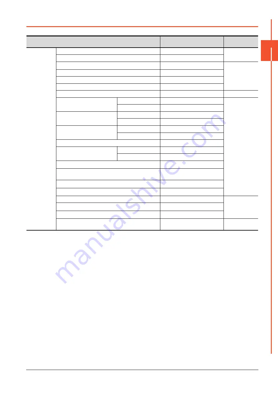
The table below shows the device ranges in [MELSEC iQ-F] as the controller type.
Device name
Setting range
Device No.
representation
Bit device
Input (X)
X0 to X1777
Octal
Output (Y)
Y0 to Y1777
Internal relay (M)
*3
M0 to M32767
Decimal
Latch relay (L)
L0 to L32767
Step relay (S)
S0 to S4095
Annunciator (F)
F0 to F32767
Link relay (B)
B0 to B7FFF
Hexadecimal
Timer
Contact (TT)
TT0 to TT1023
Decimal
Coil (TC)
TC0 to TC1023
Counter
Contact (CT)
CT0 to CT1023
Coil (CC)
CC0 to CC1023
Long counter
Contact (LCT)
LCT0 to LCT1023
Coil (LCC)
LCC0 to LCC1023
Special relay (SM)
SM0 to SM9999
Retentive timer
Contact (SS)
SS0 to SS1023
Coil (SC)
SC0 to SC1023
Servo amplifier request (SP)
*5*9
SP0 to SP6
Operation mode selection (OM)
*5*9
OM0 to OM2
OM4 to OM5
Instruction demand (for test operation) (TMB)
*5*9
TMB1 to TMB6
One-touch tuning (OTI)
*5*9
OTI0 to OTI5
Link special relay (SB)
SB0 to SB7FFF
Hexadecimal
Remote input (RX)
*8
RX0 to RX3FFF
Remote output (RY)
*8
RY0 to RY3FFF
The bit specification of the word device (except Timer, Counter,
Retentive timer, Index register(Z))
Setting range of each word device
-
Summary of Contents for GOT2000 Series
Page 2: ......
Page 84: ......
Page 432: ...6 58 6 6 Precautions ...
Page 578: ...9 54 9 6 Precautions ...
Page 726: ...12 84 12 5 Precautions ...
Page 756: ......
Page 822: ...14 66 14 4 Device Range that Can Be Set ...
Page 918: ...15 96 15 7 Precautions ...
Page 930: ...16 12 16 6 Precautions ...
Page 964: ......
Page 1002: ...19 38 19 7 Precautions ...
Page 1022: ...20 20 20 5 Precautions ...
Page 1023: ...MULTI CHANNEL FUNCTION 21 MULTI CHANNEL FUNCTION 21 1 ...
Page 1024: ......
Page 1054: ...21 30 21 5 Multi channel Function Check Sheet ...
Page 1055: ...FA TRANSPARENT FUNCTION 22 FA TRANSPARENT FUNCTION 22 1 ...
Page 1056: ......
Page 1223: ......


