17 - 8
17.4 GOT Side Settings
17.4 GOT Side Settings
17.4.1
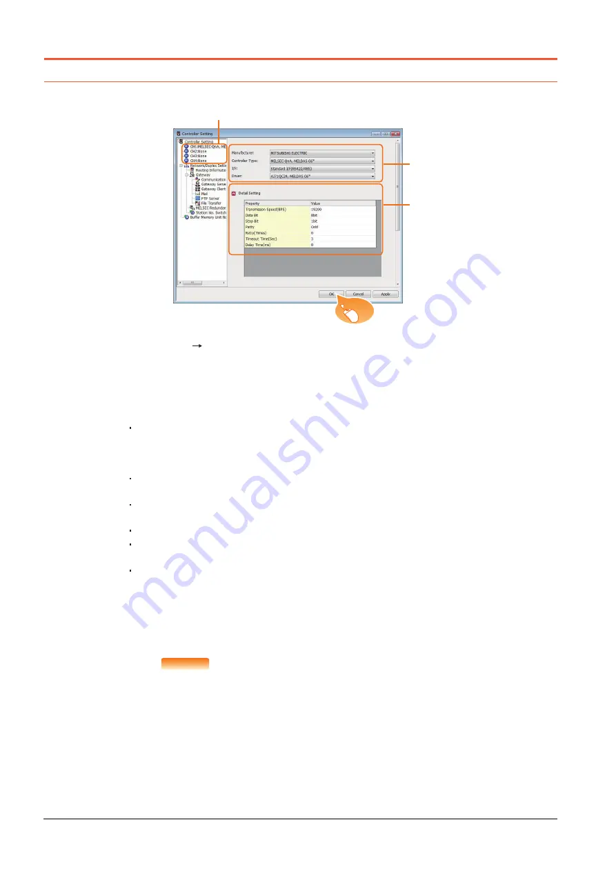
Setting communication interface (Controller Setting)
Set the channel of the connected equipment.
Step 1.
Select [Common]
[Controller Setting] from the menu.
Step 2.
The Controller Setting window is displayed. Select the channel to be used from the list menu.
Step 3.
Set the following items.
• Manufacturer: MITSUBISHI ELECTRIC
• Controller Type:
MELSEC-QnA/Q/QS, MELDAS C6*
I/F: Interface to be used
• Driver:
For direct connection to CPU
AJ71QC24, MELDAS C6*
For ELSECNET/10 connection
MELSECNET/H (used in MNET/10 mode of [Network Type])
For CC-Link (ID) connection
CC-Link Ver2 (ID)
CC-Link (ID)
For Ethernet connection
Ethernet (MELSEC), Q17nNC, CRnD-700
Step 4.
The detailed setting is displayed after Manufacturer, Controller Type, I/F, and Driver are set.
Make the settings according to the usage environment.
➠
17.4.2 Communication detail settings
Click the [OK] button when settings are completed.
POINT
POINT
POINT
The settings of connecting equipment can be confirmed in [I/F Communication Setting].
For details, refer to the following.
➠
1.1.3 I/F communication setting
2.
3.
4.
Click!
Summary of Contents for GOT2000 Series
Page 2: ......
Page 84: ......
Page 432: ...6 58 6 6 Precautions ...
Page 578: ...9 54 9 6 Precautions ...
Page 726: ...12 84 12 5 Precautions ...
Page 756: ......
Page 822: ...14 66 14 4 Device Range that Can Be Set ...
Page 918: ...15 96 15 7 Precautions ...
Page 930: ...16 12 16 6 Precautions ...
Page 964: ......
Page 1002: ...19 38 19 7 Precautions ...
Page 1022: ...20 20 20 5 Precautions ...
Page 1023: ...MULTI CHANNEL FUNCTION 21 MULTI CHANNEL FUNCTION 21 1 ...
Page 1024: ......
Page 1054: ...21 30 21 5 Multi channel Function Check Sheet ...
Page 1055: ...FA TRANSPARENT FUNCTION 22 FA TRANSPARENT FUNCTION 22 1 ...
Page 1056: ......
Page 1223: ......


