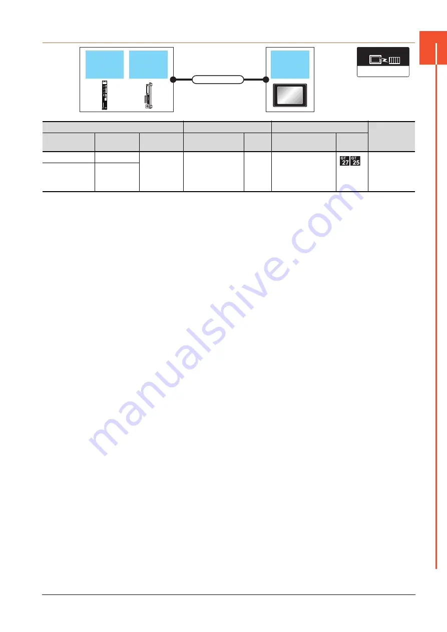
17.2 System Configuration
17 - 5
17
CNC CONNECTION
17.2.3
CC-Link connection (intelligent device station)
*1
The overall extension cable length and the length between stations vary depending on the cable type to be used and the total
number of stations.
For details, refer to the following manuals.
➠
C6/C64/C64T CONNECTION AND MAINTENANCE MANUAL BNP-B2255
➠
C6/C64/C64T NETWORK INSTRUCTION MANUAL BNP-B2373
*2
Specify Ver.1 as the mode setting in the Communication Settings to use it.
For details of the settings, refer to the following the manual.
➠
17.4.1 Setting communication interface (Controller Setting)
*3
For the specifications and inquiries of the CC-Link dedicated cable, refer to the following.
➠
CC-Link Partner Association's home page: http://www.cc-link.org/
*4
GT25-W, GT2505-V does not support the option device.
CNC
Connection cable
GOT
Number of
connectable
equipment
Model name
Expansion unit
Communication
type
Cable model
Max.
distance
Option device
*4
Model
MELDAS C6/C64
FUC6-HR865
CC-Link(ID)
CC-Link dedicated
cable
*3
*1
GT15-J61BT13
*2
26 GOTs
M700VS
M70V
FCU7-HN746
Expansion
unit
GOT
Connection cable
MELDAS
C6/C64
CC-Link Ver2(ID)
Communication driver
Summary of Contents for GOT2000 Series
Page 2: ......
Page 84: ......
Page 432: ...6 58 6 6 Precautions ...
Page 578: ...9 54 9 6 Precautions ...
Page 726: ...12 84 12 5 Precautions ...
Page 756: ......
Page 822: ...14 66 14 4 Device Range that Can Be Set ...
Page 918: ...15 96 15 7 Precautions ...
Page 930: ...16 12 16 6 Precautions ...
Page 964: ......
Page 1002: ...19 38 19 7 Precautions ...
Page 1022: ...20 20 20 5 Precautions ...
Page 1023: ...MULTI CHANNEL FUNCTION 21 MULTI CHANNEL FUNCTION 21 1 ...
Page 1024: ......
Page 1054: ...21 30 21 5 Multi channel Function Check Sheet ...
Page 1055: ...FA TRANSPARENT FUNCTION 22 FA TRANSPARENT FUNCTION 22 1 ...
Page 1056: ......
Page 1223: ......


