22.7 Personal Computer Side Setting
22 - 147
22
FA TRANSP
ARE
NT FU
NCTION
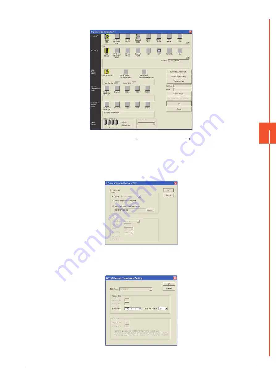
(2) When connecting the GOT and PLC in Ethernet communication
Step 1.
Click the Connection Destination view
[Connection Destination]
[(Connection
target data name)] in
the Navigation window of MT Setting/Monitoring tool for C Controller module.
Step 2.
The [Transfer Setup] is displayed.
Step 3.
Set the [Transfer Setup]:
PLC side I/F : GOT
Other station : No specification
Step 4.
Double-click [GOT] of the CPU side I/F to display [CPU side I/F Detailed Setting of GOT].
Step 5.
Mark the [via GOT(Ethernet) transparent mode] checkbox on the [CPU side I/F Detailed Setting of GOT]
screen.
Step 6.
By clicking [Set], the [GOT (Ethernet) Transparent Setting] is displayed.
Here, set the C Controller module (Q Series) (Q24DHCCPU-V), which is firstly connected via a GOT.
Summary of Contents for GOT2000 Series
Page 2: ......
Page 84: ......
Page 432: ...6 58 6 6 Precautions ...
Page 578: ...9 54 9 6 Precautions ...
Page 726: ...12 84 12 5 Precautions ...
Page 756: ......
Page 822: ...14 66 14 4 Device Range that Can Be Set ...
Page 918: ...15 96 15 7 Precautions ...
Page 930: ...16 12 16 6 Precautions ...
Page 964: ......
Page 1002: ...19 38 19 7 Precautions ...
Page 1022: ...20 20 20 5 Precautions ...
Page 1023: ...MULTI CHANNEL FUNCTION 21 MULTI CHANNEL FUNCTION 21 1 ...
Page 1024: ......
Page 1054: ...21 30 21 5 Multi channel Function Check Sheet ...
Page 1055: ...FA TRANSPARENT FUNCTION 22 FA TRANSPARENT FUNCTION 22 1 ...
Page 1056: ......
Page 1223: ......


