4 - 80
4.2 MELSEC Q Series
Step 4.
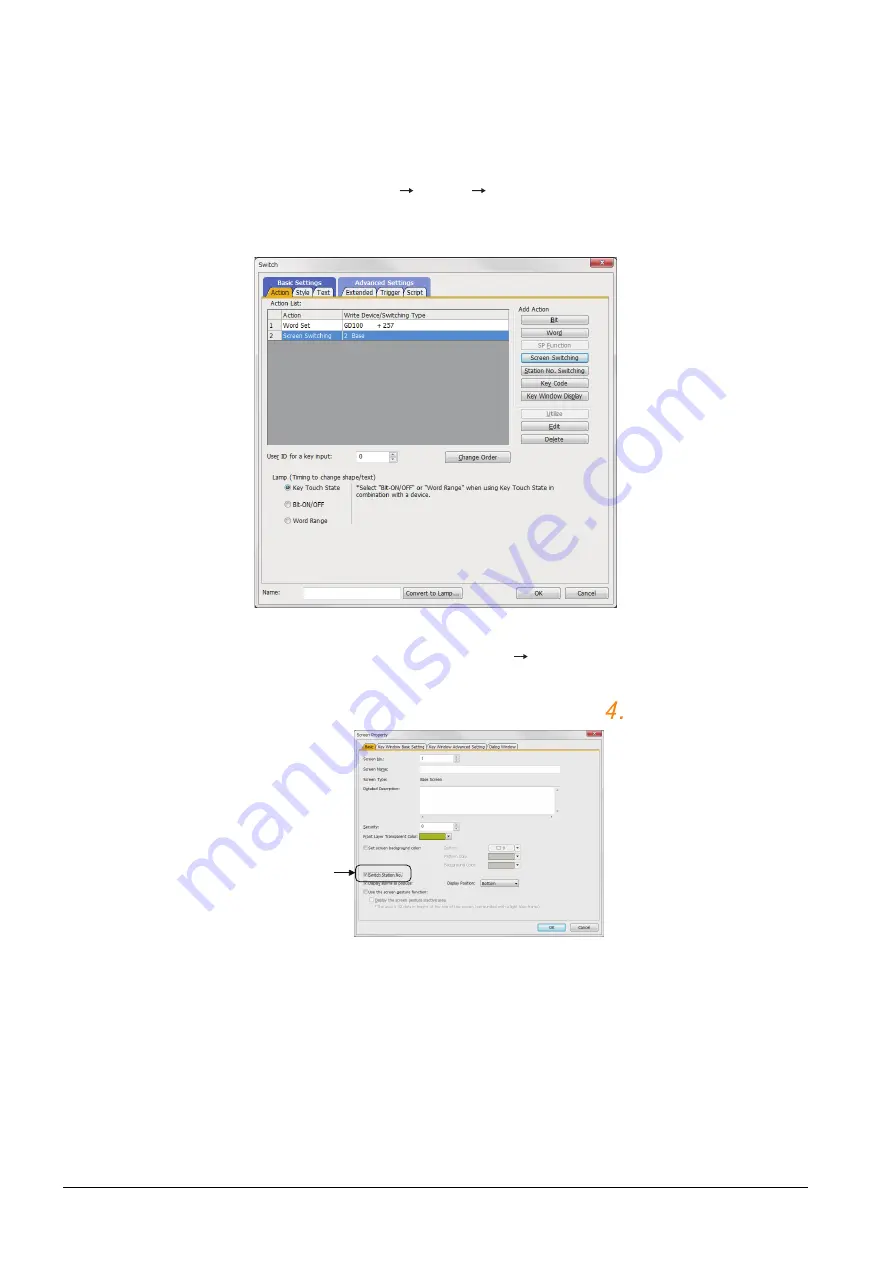
On the screen 1, set the switch for writing the station No. 1 to the station number switching device.
After the GOT is started up, the station number switching device value of the GOT is "0".
For Ethernet connection, the monitor becomes abnormal when the station number switching device value
is "0".
Therefore, set the switch for writing the station number to the station number switching device and the
switch for shifting to the monitor screen on the screen 1.
To make this setting, select [Object]
[Switch]
[Switch].
The following shows an example of setting GD100=257 (0101H: Network No. 1, Station No. 1) and base
screen=2 to one switch.(Base screen 2 is the actually monitoring screen)
Step 5.
Validate the station number switching function.
On the Basic tab screen specified by selecting [Screen]
[Property], select the item [Switch Station No.]
to validate the station number changing function.
Make this setting for each monitor screen.
However, do not make this setting on the screen 1 created in the item
above.
Check here.
Summary of Contents for GOT2000 Series
Page 2: ......
Page 84: ......
Page 432: ...6 58 6 6 Precautions ...
Page 578: ...9 54 9 6 Precautions ...
Page 726: ...12 84 12 5 Precautions ...
Page 756: ......
Page 822: ...14 66 14 4 Device Range that Can Be Set ...
Page 918: ...15 96 15 7 Precautions ...
Page 930: ...16 12 16 6 Precautions ...
Page 964: ......
Page 1002: ...19 38 19 7 Precautions ...
Page 1022: ...20 20 20 5 Precautions ...
Page 1023: ...MULTI CHANNEL FUNCTION 21 MULTI CHANNEL FUNCTION 21 1 ...
Page 1024: ......
Page 1054: ...21 30 21 5 Multi channel Function Check Sheet ...
Page 1055: ...FA TRANSPARENT FUNCTION 22 FA TRANSPARENT FUNCTION 22 1 ...
Page 1056: ......
Page 1223: ......


