


15 - 42
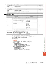
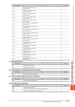
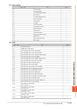
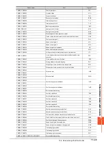
15.6 Device Range that Can Be Set
■5.
MELSERVO-J2S-*CP
*1
Use PRM0 to PRM90 when writing parameters to the servo amplifier RAM.
PRM1000 to PRM1090 are used when writing parameters to E
2
PROM of the servo amplifier.
Use PRM1000 to PRM1090 when reading parameters to the servo amplifier RAM.
*2
When writing to a point table, use the area of 1001 to 1031 (E
2
PROM area) of POS, SPD, ACT, DCT, DWL, or AUX.
If writing to the area of 1 to 31 (RAM area) of POS, SPD, ACT, DCT, DWL, or AUX, the value is not reflected.
*3
The GOT cannot read or write data from/to consecutive devices.
*4
Only reading is possible for DI0 to DI1.
POINT
POINT
POINT
Precautions for SP, OM, TMB, TMI, TMO, and TMD devices
(1) For bit devices
Only writing is possible.
[Alternate] of a bit switch cannot be used.
Use [Set], [Reset], and [Momentary] of a bit switch.
(2) For word devices, double word devices
Only writing is possible.
Numerical input cannot be used.
When writing, use [Word Set] of a data set switch.
Device name
*3
Setting range
Device No.
representation
Bit device
Servo amplifier request (SP)
SP0 to SP6
Decimal
Operation mode selection (OM)
OM0 to OM4
Instruction demand(for test operation) (TMB)
TMB0 to TMB1
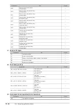
Word device
Basic parameter/expansion parameter (PRM)
*1
PRM0 to PRM90
PRM1000 to PRM1090
Status display (ST)
ST0 to ST16
Alarm (AL)
AL0 to AL1
AL11 to AL27
AL200 to AL205
AL210 to AL215
AL230 to AL235
External input (DI)
*4
DI0 to DI2
External output (DO)
DO0 to DO1
Point table (position) (POS)
*2
POS1 to POS31
POS1001 to POS1031
Point table Point table (speed) (SPD)
*2
SPD1 to SPD31
SPD1001 to SPD1031
Point table (acceleration time constant) (ACT)
*2
ACT1 to ACT31
ACT1001 to ACT1031
Point table (deceleration time constant) (DCT)
*2
DCT1 to DCT31
DCT1001 to DCT1031
Point table (dwell) (DWL)
*2
DWL1 to DWL31
DWL1001 to DWL1031
Point table (auxiliary function) (AUX)
*2
AUX1 to AUX31
AUX1001 to AUX1031
Double word device
Input signal for test operation (for test operation) (TMI)
TMI0
Forced output of signal pin (for test operation) (TMO)
TMO0
Set data (for test operation) (TMD)
TMD0 to TMD2
Summary of Contents for GOT2000 Series
Page 2: ......
Page 84: ......
Page 432: ...6 58 6 6 Precautions ...
Page 578: ...9 54 9 6 Precautions ...
Page 726: ...12 84 12 5 Precautions ...
Page 756: ......
Page 822: ...14 66 14 4 Device Range that Can Be Set ...
Page 918: ...15 96 15 7 Precautions ...
Page 930: ...16 12 16 6 Precautions ...
Page 964: ......
Page 1002: ...19 38 19 7 Precautions ...
Page 1022: ...20 20 20 5 Precautions ...
Page 1023: ...MULTI CHANNEL FUNCTION 21 MULTI CHANNEL FUNCTION 21 1 ...
Page 1024: ......
Page 1054: ...21 30 21 5 Multi channel Function Check Sheet ...
Page 1055: ...FA TRANSPARENT FUNCTION 22 FA TRANSPARENT FUNCTION 22 1 ...
Page 1056: ......
Page 1223: ......