1 - 24
1.3 Option Devices for the Respective Connection
1.3.7
Installing a unit on another unit (Checking the unit installation
position)
This section describes the precautions for installing units on another unit.
For the installation method of each unit, refer to the User's Manual for the communication unit and option unit you are using.
For the method for installing a unit on another unit, refer to the following.
➠
GOT2000 Series User's Manual (Hardware)
■1.
When using a bus connection unit
The installation position varies depending on the bus connection unit to be used.
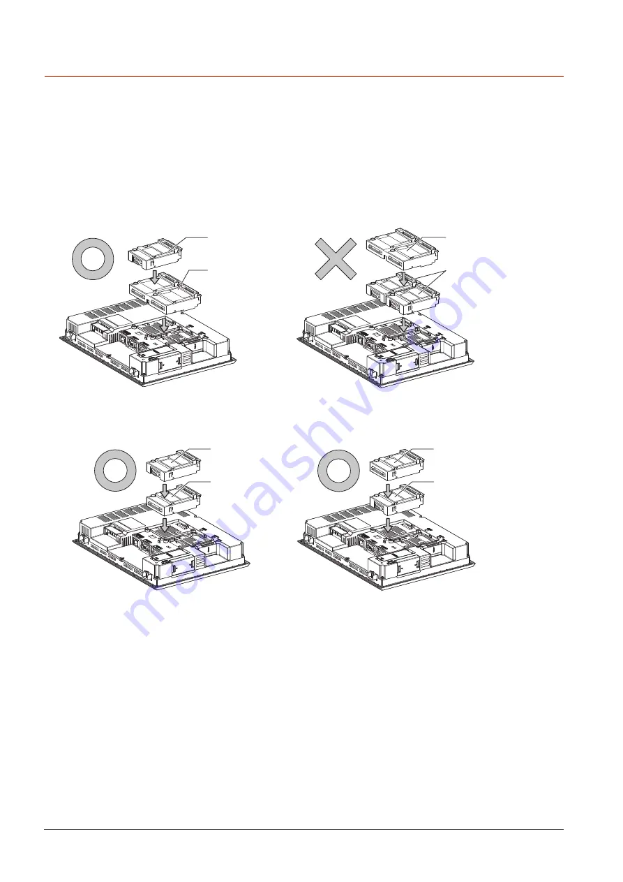
(1) Wide bus units (GT15-75QBUS(2)L, GT15-75ABUS(2)L, GT15-QBUS2, GT15-ABUS2)
Install a bus connection unit in the 1st stage of the extension interface.
If a bus connection unit is installed in the 2nd stage or above, the unit cannot be used.
Example: Installing a bus connection unit and serial communication units
(2) Standard size bus connection unit (GT15-QBUS and GT15-ABUS)
A bus connection unit can be installed in any position (1st to 3rd stage) of the extension interface.
Example: Installing a bus connection unit and serial communication units
Serial communication unit
Bus connection unit
Bus connection unit
Serial communication unit
Serial communication unit
Bus connection unit
Bus connection unit
Serial communication unit
Summary of Contents for GOT2000 Series
Page 2: ......
Page 84: ......
Page 432: ...6 58 6 6 Precautions ...
Page 578: ...9 54 9 6 Precautions ...
Page 726: ...12 84 12 5 Precautions ...
Page 756: ......
Page 822: ...14 66 14 4 Device Range that Can Be Set ...
Page 918: ...15 96 15 7 Precautions ...
Page 930: ...16 12 16 6 Precautions ...
Page 964: ......
Page 1002: ...19 38 19 7 Precautions ...
Page 1022: ...20 20 20 5 Precautions ...
Page 1023: ...MULTI CHANNEL FUNCTION 21 MULTI CHANNEL FUNCTION 21 1 ...
Page 1024: ......
Page 1054: ...21 30 21 5 Multi channel Function Check Sheet ...
Page 1055: ...FA TRANSPARENT FUNCTION 22 FA TRANSPARENT FUNCTION 22 1 ...
Page 1056: ......
Page 1223: ......


