21.2 System Configuration
21 - 5
21
MUL
T
I-CH
ANNEL FUNC
TION
21.2.2
Ethernet multiple connection
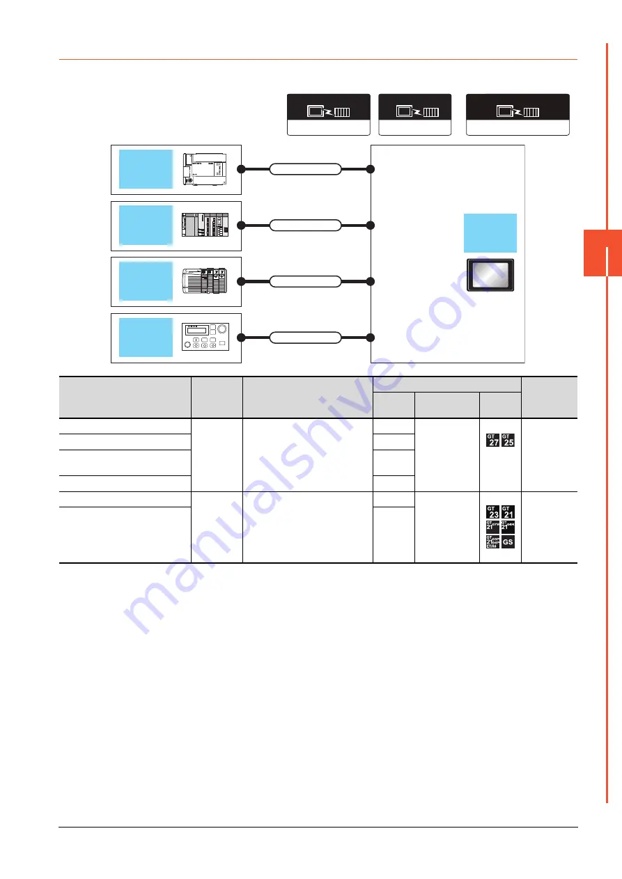
One GOT can make several Ethernet connections and the bus or network connections. Therefore, the system configuration,
in which several networks are linked, can be established.
PLC
Connection
type
Connection cable
GOT
Number of
connectable
equipment
Channel
No.
Option device
Model
MELSEC-FX
Ethernet
For the system configuration between
GOT and the controllers, refer to the
following.
➠
Each chapter indicating the
system configuration
1
Ethernet
4 connected
equipment for
1 GOT
(4 channels)
QCPU
2
ALLEN-BRADLEY
PLC
3
Robot controller
4
MELSEC-FX
Ethernet
For the system configuration between
GOT and the controllers, refer to the
following.
➠
Each chapter indicating the
system configuration
1
- (Built into GOT)
2 connected
equipment for
1 GOT
(2 channels)
QCPU
2
Ethernet (FX), Gateway
Communication driver
Ethernet/IP(AB)/
Gateway
Communication driver
Communication driver
Ethernet(MITSUBISHI ELECTRIC),Gateway
Ethernet connection
(Channel No.1)
Ethernet connection
(Channel No.2)
Ethernet connection
(Channel No.3)
Ethernet connection
(Channel No.4)
Connection cable
Connection cable
Connection cable
Connection cable
GOT
FXCPU
ALLEN-
BRADLEY
PLC
Robot
controller
QCPU
Summary of Contents for GOT2000 Series
Page 2: ......
Page 84: ......
Page 432: ...6 58 6 6 Precautions ...
Page 578: ...9 54 9 6 Precautions ...
Page 726: ...12 84 12 5 Precautions ...
Page 756: ......
Page 822: ...14 66 14 4 Device Range that Can Be Set ...
Page 918: ...15 96 15 7 Precautions ...
Page 930: ...16 12 16 6 Precautions ...
Page 964: ......
Page 1002: ...19 38 19 7 Precautions ...
Page 1022: ...20 20 20 5 Precautions ...
Page 1023: ...MULTI CHANNEL FUNCTION 21 MULTI CHANNEL FUNCTION 21 1 ...
Page 1024: ......
Page 1054: ...21 30 21 5 Multi channel Function Check Sheet ...
Page 1055: ...FA TRANSPARENT FUNCTION 22 FA TRANSPARENT FUNCTION 22 1 ...
Page 1056: ......
Page 1223: ......


