5.4 PLC Side Setting
5 - 97
5
E
T
H
E
RNET CONNEC
T
ION
■3.
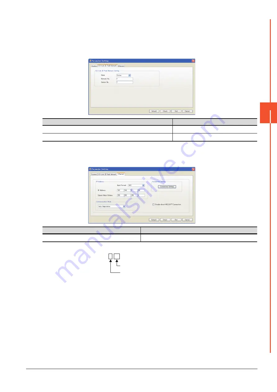
Ethernet Adapter Module setting
Set the parameter with the Ethernet adapter module setting tool.
For details of the setting method, refer to the following manual.
➠
CC-Link IE Field Network Ethernet Adapter Module User's Manual
(1) CC-Link IE Field Network setting
*1
Set the same value as the network No. set on the PLC side.
*2
Set a value other than the network No. set on the PLC side.
(2) Ethernet setting
*1
Set the IP address within the following range.
Item
Set value
Network No.
1
*1
Station No.
1
*2
Item
Set value
IP address
192.168.3.30
*1
192.168. 3. 30
Set the fourth octet within the range from 1 to 64.
Set the third octet within the range from 1 to 239.
Summary of Contents for GOT2000 Series
Page 2: ......
Page 84: ......
Page 432: ...6 58 6 6 Precautions ...
Page 578: ...9 54 9 6 Precautions ...
Page 726: ...12 84 12 5 Precautions ...
Page 756: ......
Page 822: ...14 66 14 4 Device Range that Can Be Set ...
Page 918: ...15 96 15 7 Precautions ...
Page 930: ...16 12 16 6 Precautions ...
Page 964: ......
Page 1002: ...19 38 19 7 Precautions ...
Page 1022: ...20 20 20 5 Precautions ...
Page 1023: ...MULTI CHANNEL FUNCTION 21 MULTI CHANNEL FUNCTION 21 1 ...
Page 1024: ......
Page 1054: ...21 30 21 5 Multi channel Function Check Sheet ...
Page 1055: ...FA TRANSPARENT FUNCTION 22 FA TRANSPARENT FUNCTION 22 1 ...
Page 1056: ......
Page 1223: ......


