8 - 20
8.2 System Configuration
8.2.4
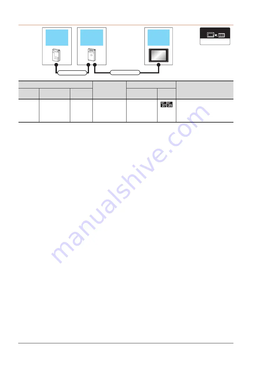
Connection to A0J2HCPU
*1
The number of connectable GOTs is restricted depending on the number of intelligent function modules mounted to the
A0J2HCPU.
➠
8.4.12 When connecting multiple GOTs
*2
When using the following functions, use GT15-QBUS(2). GT15-75QBUS(2)L cannot be used.
Remote personal computer operation (Serial), video display function, multimedia function, external I/O device, RGB display
function, sound output function
*3
GT25-W, GT2505-V does not support the option device.
PLC
Connection cable 2)
GOT
*1
Max. distance
Model name
Connection cable 1)
Power supply
module
Option device
*2*3
Model
A0J2HCPU
A0J2C03(0.3m)
A0J2C06(0.55m)
A0J2C10(1m)
A0J2C20(2m)
A0J2-PW
GT15-J2C10B(1m)
GT15-75ABUSL
GT15-75ABUS2L
GT15-ABUS
GT15-ABUS2
Between PLC and GOT: 6.6m
Between power supply module and
GOT: 1m
Power supply
module
GOT
PLC
Connection cable 2)
Connection cable 1)
Communication driver
Bus(A/QnA)
Summary of Contents for GOT2000 Series
Page 2: ......
Page 84: ......
Page 432: ...6 58 6 6 Precautions ...
Page 578: ...9 54 9 6 Precautions ...
Page 726: ...12 84 12 5 Precautions ...
Page 756: ......
Page 822: ...14 66 14 4 Device Range that Can Be Set ...
Page 918: ...15 96 15 7 Precautions ...
Page 930: ...16 12 16 6 Precautions ...
Page 964: ......
Page 1002: ...19 38 19 7 Precautions ...
Page 1022: ...20 20 20 5 Precautions ...
Page 1023: ...MULTI CHANNEL FUNCTION 21 MULTI CHANNEL FUNCTION 21 1 ...
Page 1024: ......
Page 1054: ...21 30 21 5 Multi channel Function Check Sheet ...
Page 1055: ...FA TRANSPARENT FUNCTION 22 FA TRANSPARENT FUNCTION 22 1 ...
Page 1056: ......
Page 1223: ......


