


9 - 38
9.5 PLC side setting when connecting to MELSEC/10
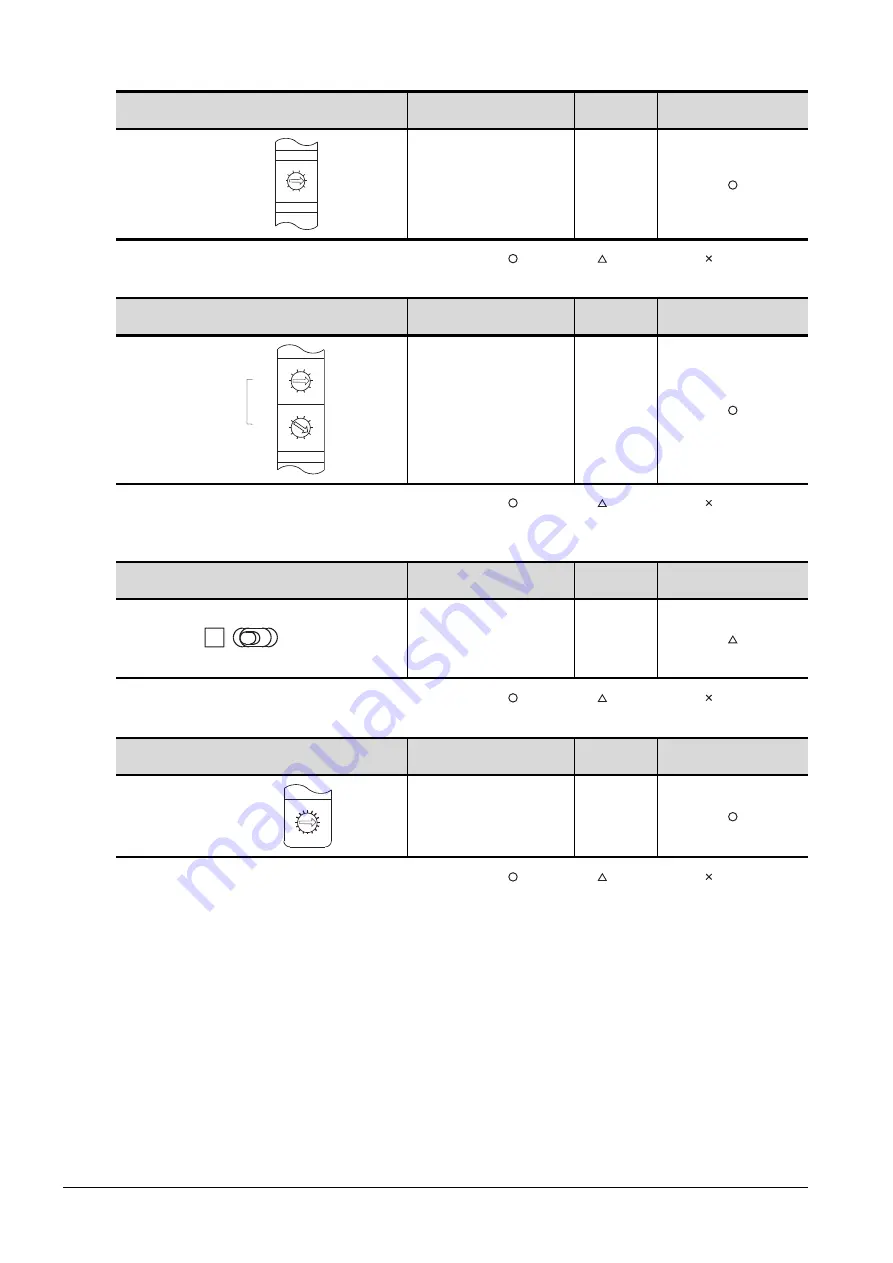
(2) Group number setting switch
: Necessary : As necessary : Not necessary
(3) Station number setting switch
: Necessary : As necessary : Not necessary
*1
Do not set the same station No. as that of the GOT.
(4) LED indication select switch
: Necessary : As necessary : Not necessary
(5) Mode setting switch
: Necessary : As necessary : Not necessary
Group number setting switch
Description
Set value
Setting necessity at GOT
connection
Group No. setting
(No group setting)
0
(fixed)
Station number setting switch
Description
Set value
Setting necessity at GOT
connection
Station number setting
(Station No.1)
*1
1
LED indication select switch
Description
Set value
Setting necessity at GOT
connection
LED indication select
L (F.L.)
Mode setting switch
Description
Set value
Setting necessity at GOT
connection
Mode setting
(Online)
0
(fixed)
3
2
0
5
9
4
8
7
6
1
GROUP.NO.
3
2
0
5
9
4
8
7
6
1
3
2
0
5
9
4
8
7
6
1
STATION.NO.
X10
X1
L
R
DISPLAY
(F.L) (R.L.)
F
7
E
6
D
5
C
4
B
3
A
2
9
1
0
8
MODE
0 : ONLINE(A.R)
2 : OFFLINE
Summary of Contents for GOT2000 Series
Page 2: ......
Page 84: ......
Page 432: ...6 58 6 6 Precautions ...
Page 578: ...9 54 9 6 Precautions ...
Page 726: ...12 84 12 5 Precautions ...
Page 756: ......
Page 822: ...14 66 14 4 Device Range that Can Be Set ...
Page 918: ...15 96 15 7 Precautions ...
Page 930: ...16 12 16 6 Precautions ...
Page 964: ......
Page 1002: ...19 38 19 7 Precautions ...
Page 1022: ...20 20 20 5 Precautions ...
Page 1023: ...MULTI CHANNEL FUNCTION 21 MULTI CHANNEL FUNCTION 21 1 ...
Page 1024: ......
Page 1054: ...21 30 21 5 Multi channel Function Check Sheet ...
Page 1055: ...FA TRANSPARENT FUNCTION 22 FA TRANSPARENT FUNCTION 22 1 ...
Page 1056: ......
Page 1223: ......