5.4 PLC Side Setting
5 - 99
5
E
T
H
E
RNET CONNEC
T
ION
5.4.16
Connecting to PERIPHERAL I/F (Built-in Ethernet port Motion
Controller CPU)
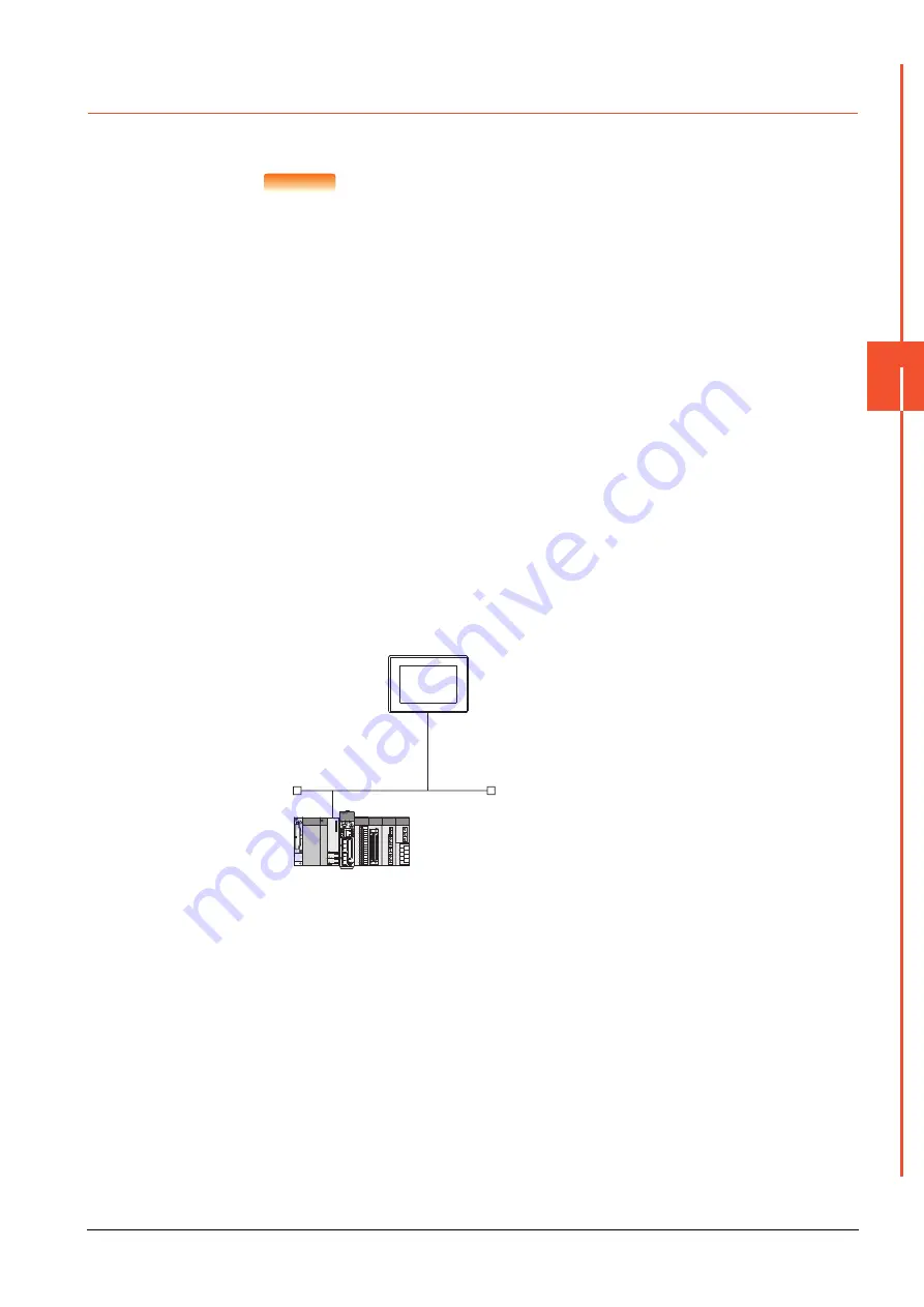
This section describes the settings of the GOT and Built-in Ethernet port Motion Controller CPU in the following case of
system configuration.
POINT
POINT
POINT
(1) GOT type setting
For details, refer to the following.
➠
1.1.1 Setting connected equipment (Channel setting)
(2) Setting [Controller Type]
(2) CPU No. specification of Q170MCPU and Q170MSCPU(-S1)
Set whether to monitor the PLC CPU area or the Motion CPU area of Q170MCPU or
Q170MSCPU(-S1), in the CPU No. specification.
For details, refer to the following.
➠
(3) PLC type of GX Works2/GX Developer
When creating a program, set the following PLC type:
• For Q173D(S)CPU/Q172D(S)CPU
QnUD(E)(H)CPU
• For Q170MCPU and Q170MSCPU(-S1) Q03UDCPU
Q03UDCPU
(4) Built-in Ethernet port CPU
For details of Built-in Ethernet port CPU, refer to the following manual.
➠
User's Manual of Q173D(S)CPU/Q172D(S)CPU , Q170MCPU, and Q170MS(-
S1)CPU
■1.
System configuration
Leave the Built-in Ethernet port Motion Controller CPU settings as default in the following system configuration.
*1
For the settings when using system devices including a hub and a transceiver, refer to the following.
➠
5.4.7 Connecting to MELSEC-Q/L Series built-in Ethernet port CPU (multiple connection)
*2
These setting items do not exist at the PLC side. However, the virtual values must be set on the GOT side.
➠
3. [Controller Setting] and [Ethernet] of GT Designer3
<GOT>
(The settings other than the
following are set to the default)
*1
*2
*2
Network No.
: 1
PLC No.
: 1
IP address
: 192.168.3.18
Port No.
: 5001
Communication
format
: UDP (fixed)
Network No.
: 1 (virtual)
PLC No.
: 2 (virtual)
IP address
: 192.168.3.39
Open system
: MELSOFT connection (fixed)
<Connecting to Built-in Ethernet port CPU>
(The following settings are set to the default)
Summary of Contents for GOT2000 Series
Page 2: ......
Page 84: ......
Page 432: ...6 58 6 6 Precautions ...
Page 578: ...9 54 9 6 Precautions ...
Page 726: ...12 84 12 5 Precautions ...
Page 756: ......
Page 822: ...14 66 14 4 Device Range that Can Be Set ...
Page 918: ...15 96 15 7 Precautions ...
Page 930: ...16 12 16 6 Precautions ...
Page 964: ......
Page 1002: ...19 38 19 7 Precautions ...
Page 1022: ...20 20 20 5 Precautions ...
Page 1023: ...MULTI CHANNEL FUNCTION 21 MULTI CHANNEL FUNCTION 21 1 ...
Page 1024: ......
Page 1054: ...21 30 21 5 Multi channel Function Check Sheet ...
Page 1055: ...FA TRANSPARENT FUNCTION 22 FA TRANSPARENT FUNCTION 22 1 ...
Page 1056: ......
Page 1223: ......


