15 - 54
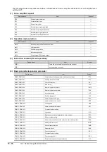
15.6 Device Range that Can Be Set
The following shows correspondences between virtual devices for servo amplifier and data of the servo amplifier used
with the GOT.
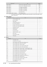
(1) Servo amplifier request
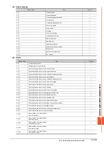
(2) Operation mode selection
(3) Instruction demand (for test operation)
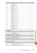
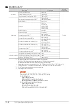
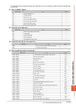
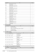
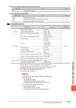
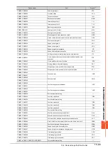
(4) Basic parameter/expansion parameter
*1
For the parameters prefixed by an asterisk (*), setting becomes effective when the power is turned off once and back on after
setting the parameter data.
Device name
Item
Symbol
SP0
Status display data clear
―
SP1
Current alarm clear
―
SP2
Alarm history clear
―
SP3
External input signal prohibited
―
SP4
External output signal prohibited
―
SP5
External input signal resumed
―
SP6
External output signal resumed
―
Device name
Item
Symbol
OM0
Normal mode (not test operation mode)
―
OM1
JOG operation
―
OM2
Positioning operation
―
OM3
Motorless operation
―
OM4
Output signal (DO) forced output
―
Device name
Item
Symbol
TMB1
Temporary stop command
―
TMB2
Test operation (positioning operation) start command
―
TMB3
Forward rotation direction
―
TMB4
Reverse rotation direction
―
TMB5
Restart for remaining distance
―
TMB6
Remaining distance clear
―
Device name
Item
Symbol
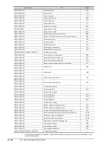
*1
PA1, PA1001
Control mode
*STY
PA2, PA1002
Regenerative brake option
*REG
PA3, PA1003
Absolute position detection system
*ABS
PA4, PA1004
Function selection A-1
*AOP1
PA5, PA1005
Number of command input pulses per revolution
*FBP
PA6, PA1006
Electronic gear numerator
(command pulse multiplying factor numerator)
CMX
PA7, PA1007
Electronic gear denominator
(command pulse multiplying factor denominator)
CDV
PA8, PA1008
Auto tuning mode
ATU
PA9, PA1009
Auto tuning response
RSP
PA10, PA1010
In-position range
INP
PA11, PA1011
Forward torque limit
TLP
PA12, PA1012
Reverses torque limit
TLN
PA13, PA1013
Command pulse input form
*PLSS
PA14, PA1014
Rotation direction selection
*POL
PA15, PA1015
Encoder output pulses
*ENR
PA16 to PA18, PA1016 to PA1018
For manufacturer setting
―
PA19, PA1019
Parameter block
*BLK
Summary of Contents for GOT2000 Series
Page 2: ......
Page 84: ......
Page 432: ...6 58 6 6 Precautions ...
Page 578: ...9 54 9 6 Precautions ...
Page 726: ...12 84 12 5 Precautions ...
Page 756: ......
Page 822: ...14 66 14 4 Device Range that Can Be Set ...
Page 918: ...15 96 15 7 Precautions ...
Page 930: ...16 12 16 6 Precautions ...
Page 964: ......
Page 1002: ...19 38 19 7 Precautions ...
Page 1022: ...20 20 20 5 Precautions ...
Page 1023: ...MULTI CHANNEL FUNCTION 21 MULTI CHANNEL FUNCTION 21 1 ...
Page 1024: ......
Page 1054: ...21 30 21 5 Multi channel Function Check Sheet ...
Page 1055: ...FA TRANSPARENT FUNCTION 22 FA TRANSPARENT FUNCTION 22 1 ...
Page 1056: ......
Page 1223: ......

