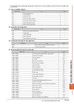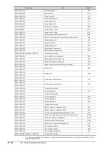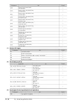
15.6 Device Range that Can Be Set
15 - 57
SER
V
O
AMPLIFIER CONNECTION
15
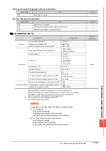
(7) I/O setting parameter
*1
For the parameters prefixed by an asterisk (*), setting becomes effective when the power is turned off once and back on after
setting the parameter data.
(8) Status display
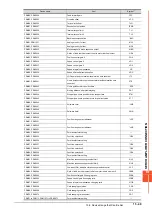
Device name
Item
Symbol
*1
PD1, PD1001
Input signal automatic ON selection 1
*DIA1
PD2, PD1002
For manufacturer setting
―
PD3, PD1003
Input signal device selection 1 (CN1-15)
*DI1
PD4, PD1004
Input signal device selection 2 (CN1-16)
*DI2
PD5, PD1005
Input signal device selection 3 (CN1-17)
*DI3
PD6, PD1006
Input signal device selection 4 (CN1-18)
*DI4
PD7, PD1007
Input signal device selection 5 (CN1-19)
*DI5
PD8, PD1008
Input signal device selection 6 (CN1-41)
*DI6
PD9, PD1009
For manufacturer setting
―
PD10, D1010
Input signal device selection 8 (CN1-43)
*DI8
PD11, PD1011
Input signal device selection 9 (CN1-44)
*DI9
PD12, PD1012
Input signal device selection 10 (CN1-45)
*DI10
PD13, PD1013
Output signal device selection 1 (CN1-22)
*DO1
PD14, PD1014
Output signal device selection 2 (CN1-23)
*DO2
PD15, PD1015
Output signal device selection 3 (CN1-24)
*DO3
PD16, PD1016
Output signal device selection 4 (CN1-25)
*DO4
PD17, PD1017
For manufacturer setting
―
PD18, PD1018
Output signal device selection 6 (CN1-49)
*DO6
PD19, PD1019
Response level setting
*DIF
PD20, 1020
Function selection D-1
*DOP1
PD21, PD1021
For manufacturer setting
―
PD22, PD1022
Function selection D-3
*DOP3
PD23, PD1023
For manufacturer setting
―
PD24, PD1024
Function selection D-5
*DOP5
PD25 to PD30, PD1025 to PD1030
For manufacturer setting
―
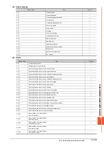
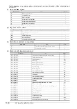
Device name
Item
Symbol
ST0
Cumulative feedback pulses
―
ST1
Servo motor speed
―
ST2
Droop pulses
―
ST3
Cumulative command pulses
―
ST4
Command pulse frequency
―
ST5
Analog speed command voltage/limit voltage
―
ST6
Analog torque command voltage/limit voltage
―
ST7
Regenerative load ratio
―
ST8
Effective load ratio
―
ST9
Peak load ratio
―
ST10
Instantaneous torque
―
ST11
Within one-revolution position
―
ST12
ABS counter
―
ST13
Load inertia moment ratio
―
ST14
Bus voltage
―
Summary of Contents for GOT2000 Series
Page 2: ......
Page 84: ......
Page 432: ...6 58 6 6 Precautions ...
Page 578: ...9 54 9 6 Precautions ...
Page 726: ...12 84 12 5 Precautions ...
Page 756: ......
Page 822: ...14 66 14 4 Device Range that Can Be Set ...
Page 918: ...15 96 15 7 Precautions ...
Page 930: ...16 12 16 6 Precautions ...
Page 964: ......
Page 1002: ...19 38 19 7 Precautions ...
Page 1022: ...20 20 20 5 Precautions ...
Page 1023: ...MULTI CHANNEL FUNCTION 21 MULTI CHANNEL FUNCTION 21 1 ...
Page 1024: ......
Page 1054: ...21 30 21 5 Multi channel Function Check Sheet ...
Page 1055: ...FA TRANSPARENT FUNCTION 22 FA TRANSPARENT FUNCTION 22 1 ...
Page 1056: ......
Page 1223: ......

