1.4 Connection Cables for the Respective Connection
1 - 35
1
PREP
ARA
T
O
R
Y PROC
EDURE
S FOR MONIT
O
RING
■5.
GT23
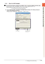
Set the terminating resistor using the terminating resistor setting switch.
*1
The default setting is "Disable".
• For GT2310-V
■6.
GT21
Set the terminating resistor using the terminating resistor selector.
• For GT2103-PMBD
Terminating resistor
*1
Switch No.
1
2
100 OHM
ON
ON
Disable
OFF
OFF
ON
1
2
Terminating resistor setting switch
(inside the cover)
USB
Terminating resistor selector switch
Summary of Contents for GOT2000 Series
Page 2: ......
Page 84: ......
Page 432: ...6 58 6 6 Precautions ...
Page 578: ...9 54 9 6 Precautions ...
Page 726: ...12 84 12 5 Precautions ...
Page 756: ......
Page 822: ...14 66 14 4 Device Range that Can Be Set ...
Page 918: ...15 96 15 7 Precautions ...
Page 930: ...16 12 16 6 Precautions ...
Page 964: ......
Page 1002: ...19 38 19 7 Precautions ...
Page 1022: ...20 20 20 5 Precautions ...
Page 1023: ...MULTI CHANNEL FUNCTION 21 MULTI CHANNEL FUNCTION 21 1 ...
Page 1024: ......
Page 1054: ...21 30 21 5 Multi channel Function Check Sheet ...
Page 1055: ...FA TRANSPARENT FUNCTION 22 FA TRANSPARENT FUNCTION 22 1 ...
Page 1056: ......
Page 1223: ......


