15 - 50
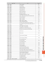
15.6 Device Range that Can Be Set
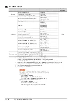
*1
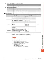
For the parameters prefixed by an asterisk (*), setting becomes effective when the power is turned off once and back on after
setting the parameter data.
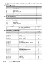
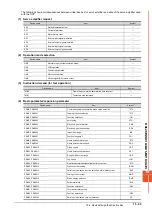
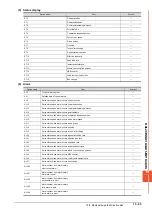
(5) Status display
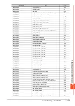
(6) Alarm
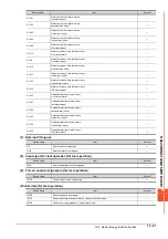
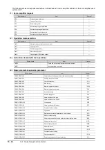
PRM74, PRM1074
OUT1 output time selection
OUT1
PRM75, PRM1075
OUT2 output time selection
OUT2
PRM76, PRM1076
OUT3 output time selection
OUT3
PRM77, PRM1077
Selected to program input polarity selection 1
SYC1
PRM78 to PRM90, PRM1078 to PRM1090
For manufacturer setting
―
Device name
Item
Symbol
ST0
Current position
―
ST1
Command position
―
ST2
Command remaining distance
―
ST3
Program Number
―
ST4
Step Number
―
ST5
Cumulative feedback pulses
―
ST6
Servo motor speed
―
ST7
Droop pulses
―
ST8
Override
―
ST9
Torque limit voltage
―
ST10
Regenerative load ratio
―
ST11
Effective load ratio
―
ST12
Peak load ratio
―
ST13
Instantaneous torque
―
ST14
Within one-revolution position
―
ST15
ABS counter
―
ST16
Load inertia moment ratio
―
ST17
Bus voltage
―
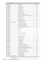
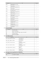
Device name
Item
Symbol
AL0
Current alarm number
―
AL1
Detailed data of current alarms
―
AL11
Servo status when alarm occurs Current position
―
AL12
Servo status when alarm occurs Command position
―
AL13
Servo status when alarm occurs Command remaining distance
―
AL14
Servo status when alarm occurs Program Number
―
AL15
Servo status when alarm occurs Step Number
―
AL16
Servo status when alarm occurs Cumulative feedback pulses
―
AL17
Servo status when alarm occurs Servo motor speed
―
AL18
Servo status when alarm occurs Droop pulses
―
AL19
Servo status when alarm occurs Override
―
AL20
Servo status when alarm occurs Torque limit voltage
―
AL21
Servo status when alarm occurs Regenerative load ratio
―
AL22
Servo status when alarm occurs Effective load ratio
―
AL23
Servo status when alarm occurs Peak load ratio
―
AL24
Servo status when alarm occurs Instantaneous torque
―
AL25
Servo status when alarm occurs Within one-revolution position
―
AL26
Servo status when alarm occurs ABS counter
―
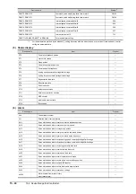
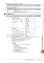
Device name
Item
Symbol
*1
Summary of Contents for GOT2000 Series
Page 2: ......
Page 84: ......
Page 432: ...6 58 6 6 Precautions ...
Page 578: ...9 54 9 6 Precautions ...
Page 726: ...12 84 12 5 Precautions ...
Page 756: ......
Page 822: ...14 66 14 4 Device Range that Can Be Set ...
Page 918: ...15 96 15 7 Precautions ...
Page 930: ...16 12 16 6 Precautions ...
Page 964: ......
Page 1002: ...19 38 19 7 Precautions ...
Page 1022: ...20 20 20 5 Precautions ...
Page 1023: ...MULTI CHANNEL FUNCTION 21 MULTI CHANNEL FUNCTION 21 1 ...
Page 1024: ......
Page 1054: ...21 30 21 5 Multi channel Function Check Sheet ...
Page 1055: ...FA TRANSPARENT FUNCTION 22 FA TRANSPARENT FUNCTION 22 1 ...
Page 1056: ......
Page 1223: ......


