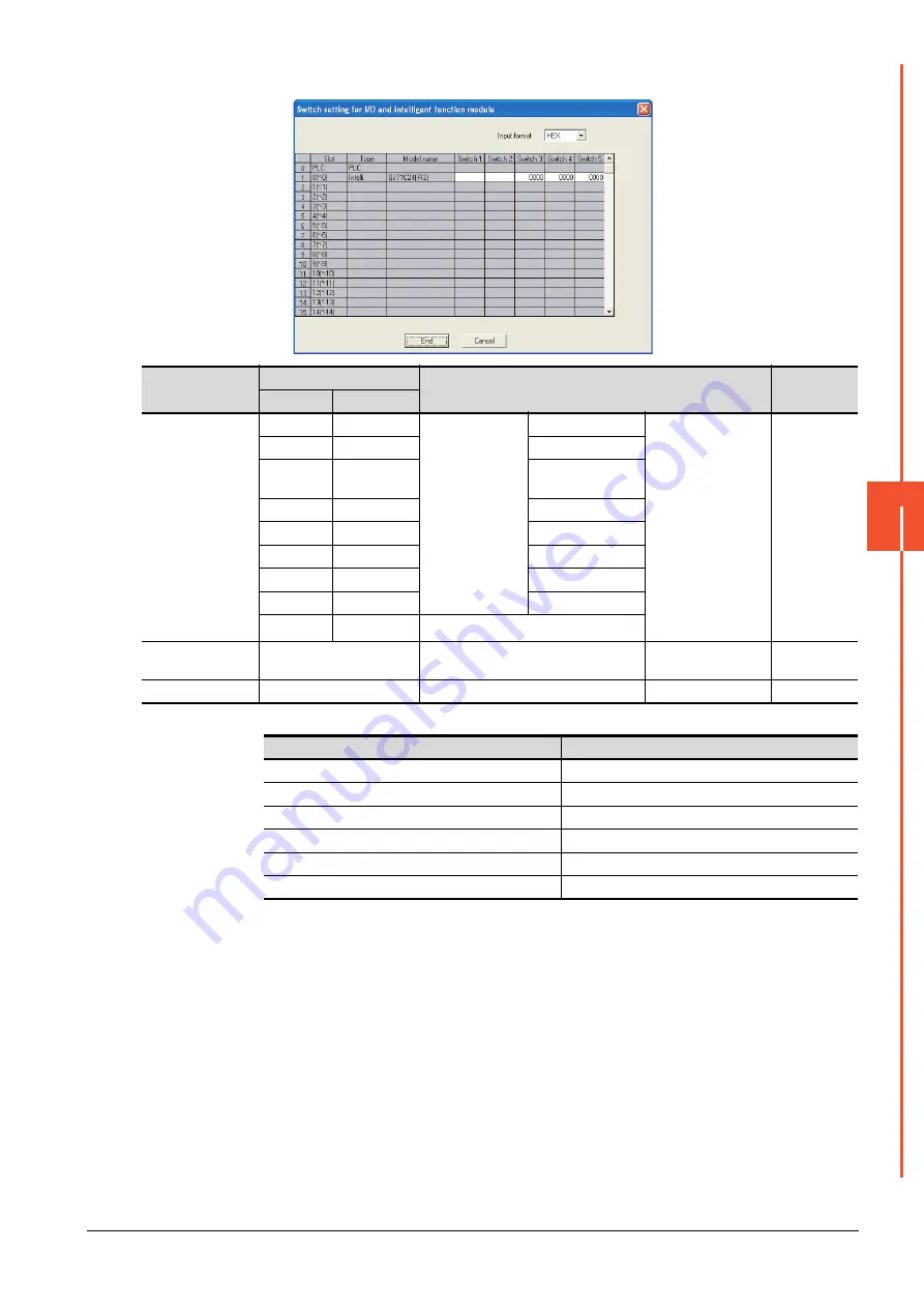
7.5 PLC Side Setting
7 - 37
7
S
E
RIAL COMMUNICA
TION CONNEC
T
ION
(2) When connecting to the CH2 side
*1
The module operates under the following transmission specifications.
*2
The serial communication module operates at the transmission speed set on the GOT.
*3
When the value of switch setting is other than "0", the setting of [Format] and [Transmission Speed] on the GOT side are required
to be changed.
➠
7.4.2 Communication detail settings
Switch
No.
Bit
Description
Set value
*3
Position
Specified value
Switch 3
b0
OFF
CH2
transmission
settings
*1
Operation setting
(Operates according to
the GOT side
specifications.)
0000H
b1
OFF
Data bit
b2
OFF
Parity
bit
b3
OFF
Even/odd parity
b4
OFF
Stop bit
b5
OFF
Sum check code
b6
OFF
Write during RUN
b7
OFF
Setting modifica-tions
b8 to b15
―
CH2 transmission speed setting
*2
Switch 4
―
CH2 Communication protocol setting
GX Developer
connection
0000H
Switch 5
―
Station number setting
0th station
0000H
Transmission specifications
Setting details
Operation setting
Independent
Data bit
8bits
Parity bit
Yes
Even/odd parity
Odd
Stop bit
1bit
Sum check code
Yes
Summary of Contents for GOT2000 Series
Page 2: ......
Page 84: ......
Page 432: ...6 58 6 6 Precautions ...
Page 578: ...9 54 9 6 Precautions ...
Page 726: ...12 84 12 5 Precautions ...
Page 756: ......
Page 822: ...14 66 14 4 Device Range that Can Be Set ...
Page 918: ...15 96 15 7 Precautions ...
Page 930: ...16 12 16 6 Precautions ...
Page 964: ......
Page 1002: ...19 38 19 7 Precautions ...
Page 1022: ...20 20 20 5 Precautions ...
Page 1023: ...MULTI CHANNEL FUNCTION 21 MULTI CHANNEL FUNCTION 21 1 ...
Page 1024: ......
Page 1054: ...21 30 21 5 Multi channel Function Check Sheet ...
Page 1055: ...FA TRANSPARENT FUNCTION 22 FA TRANSPARENT FUNCTION 22 1 ...
Page 1056: ......
Page 1223: ......


