11.4 PLC Side Setting
11 - 19
CC
-Link IE FIELD NETWOR
K CON
N
ECTION
11
POINT
POINT
POINT
Routing parameter setting of request source
Routing parameter setting is also necessary for the request source GOT.
For the setting, refer to the following.
➠
11.3.3 Routing parameter setting
■3.
GT Designer3 [Communication settings] of System configuration (Network Type: CC IE
Field)
POINT
POINT
POINT
[Controller Setting] of GT Designer3
For the setting method of [Controller Setting] of GT Designer3, refer to the following.
➠
11.3.1 Setting communication interface (Controller Setting)
11.4.3
Connecting to MELSEC-Q/L series
■1.
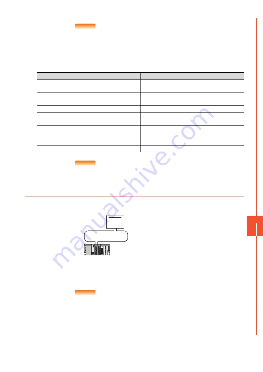
System configuration (Network Type: CC IE Field)
*1
The CC-Link IE Field Network module is mounted on slot 0 of the base unit.
The start I/O No. of the CC-Link IE Field Network module is set at [0].
POINT
POINT
POINT
When connecting to Q170MCPU or Q170MSCPU(-S1)
When connected to Q170MCPU or Q170MSCPU(-S1), the start I/O No. of the CC-Link IE Field
Network communication unit is set to "70".
Item
Set value
Network Type
CC IE Field
Network No.
1: Network No.1
Station No.
1: Station No.1
Group No.
0 (fixed)
Mode Setting
Online
Refresh Interval
25ms (Use default value)
Input for Err. Sta.
Clear (Use default value)
Retry
3times (Use default value)
Timeout Time
3sec (Use default value)
Delay Time
0ms (Use default value)
Monitor Speed
High (Normal) (Use default value)
<CC-Link IE Field Network module> *
1
(Use the default value for settings other than the following.)
Station No.
: 0 (fixed)
Mode
: Online (normal)
Network type
: CC IE Field (Master station)
Network No.
: 1
Total stations
: 1
Network Configuration Settings :
CC-Link IE Field Network
<GOT>
(Use the default value for settings other
than the following.)
RX/RY00
H
to FFH
RW
W/
RW
r
00
H
to FFH
Network type
: CC IE Field
Network No.
: 1
Station No.
: 1
Mode Setting : Online
Network Configuration Settings :
Monitor Speed : High
RX/RY00 to FFH
RW
W/
RW
r
00 to FFH
Summary of Contents for GOT2000 Series
Page 2: ......
Page 84: ......
Page 432: ...6 58 6 6 Precautions ...
Page 578: ...9 54 9 6 Precautions ...
Page 726: ...12 84 12 5 Precautions ...
Page 756: ......
Page 822: ...14 66 14 4 Device Range that Can Be Set ...
Page 918: ...15 96 15 7 Precautions ...
Page 930: ...16 12 16 6 Precautions ...
Page 964: ......
Page 1002: ...19 38 19 7 Precautions ...
Page 1022: ...20 20 20 5 Precautions ...
Page 1023: ...MULTI CHANNEL FUNCTION 21 MULTI CHANNEL FUNCTION 21 1 ...
Page 1024: ......
Page 1054: ...21 30 21 5 Multi channel Function Check Sheet ...
Page 1055: ...FA TRANSPARENT FUNCTION 22 FA TRANSPARENT FUNCTION 22 1 ...
Page 1056: ......
Page 1223: ......


