


4 - 78
4.2 MELSEC Q Series
POINT
POINT
POINT
When the MELSECNET/H network is connected to the redundant system only, SW56 (current
control station) can be set as the station number switching device.
In this case, even if the system switching occurs, the GOT always monitors the station number
that is currently the control station.
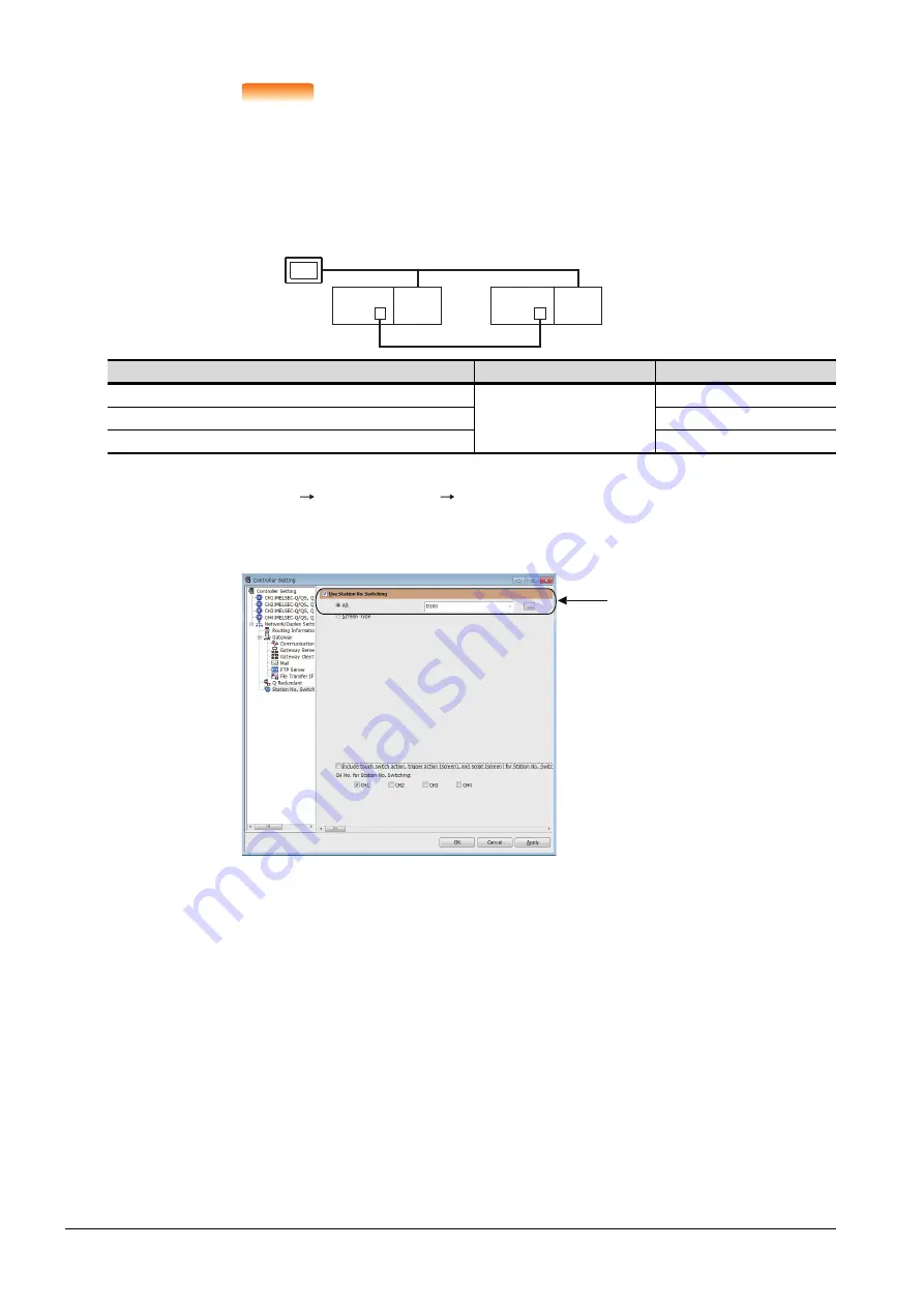
(2) Setting method (Ethernet connection)
System configuration example 2: Ethernet connection
Step 1.
Set the station number switching device.
Select [Common]
[Controller Setting]
[Station No. Switching], and set the internal device GD100 as
the station number switching device.
Do not use a device of PLC CPU as a screen switching device. Since the device information is transferred
by the tracking transfer function of the redundant system, the trigger action may be disabled.
Connected module
Network No.
Station No.
Ethernet module of control system
1
1
Ethernet module of standby system
2
GOT connected to the Ethernet network
3
Ethernet
Network No. 1
GOT
Station No. 3
Control system
(System A)
Q25PRH
CPU
QJ71
E71
Standby system
(System B)
Station No. 1
Q25PRH
CPU
QJ71
E71
Station No. 2
Set here.
Summary of Contents for GOT2000 Series
Page 2: ......
Page 84: ......
Page 432: ...6 58 6 6 Precautions ...
Page 578: ...9 54 9 6 Precautions ...
Page 726: ...12 84 12 5 Precautions ...
Page 756: ......
Page 822: ...14 66 14 4 Device Range that Can Be Set ...
Page 918: ...15 96 15 7 Precautions ...
Page 930: ...16 12 16 6 Precautions ...
Page 964: ......
Page 1002: ...19 38 19 7 Precautions ...
Page 1022: ...20 20 20 5 Precautions ...
Page 1023: ...MULTI CHANNEL FUNCTION 21 MULTI CHANNEL FUNCTION 21 1 ...
Page 1024: ......
Page 1054: ...21 30 21 5 Multi channel Function Check Sheet ...
Page 1055: ...FA TRANSPARENT FUNCTION 22 FA TRANSPARENT FUNCTION 22 1 ...
Page 1056: ......
Page 1223: ......