15.3 Connection Diagram
15 - 17
SER
V
O
AMPLIFIER CONNECTION
15
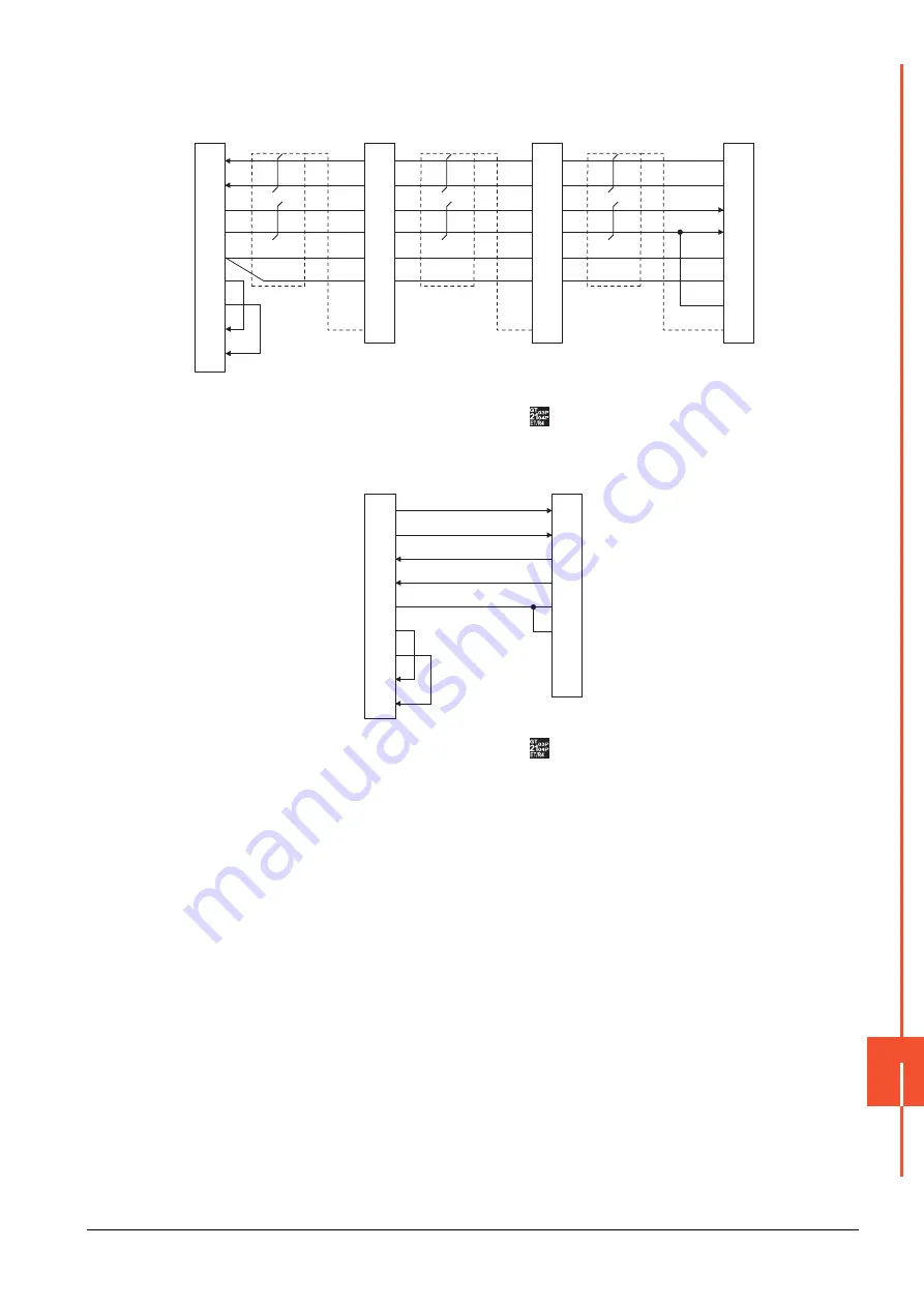
(6) RS-422 connection diagram 6)
*1
At the last axis, connect TRE to RDN.
*2
The signals RSA, RSB, CSA, and CSB are not provided for
. Return connection is not required.
(7) RS-422 connection diagram 7)
*1
The signals RSA, RSB, CSA, and CSB are not provided for
. Return connection is not required.
GOT side
Connector for interface unit's
or
2nd axis servo amplifier's CN3
Connector for interface unit's
or
1st axis servo amplifier's CN3
SDP
SDN
RDP
RDN
LG
LG
TRE
SDP
SDN
RDP
RDN
LG
LG
TRE
RDA
RDB
SDA
SDB
SG
RSA
RSB
CSA
CSB
9
19
5
15
11
1
10
Plate
9
19
5
15
11
1
10
Plate
SDP
SDN
RDP
RDN
LG
LG
TRE
9
19
5
15
11
1
10
Plate
*2
*2
*2
*2
Connector for interface unit's
or
32nd axis (last axis) CN3)
*1
GOT side
Distributor side
(Modular connector)
3
6
5
4
1
7
2
8
SDA
SDB
RDA
RDB
SG
RSA
RSB
CSA
CSB
*1
*1
*1
*1
RDP
RDN
SDP
SDN
LG
LG
P5D
NC
Summary of Contents for GOT2000 Series
Page 2: ......
Page 84: ......
Page 432: ...6 58 6 6 Precautions ...
Page 578: ...9 54 9 6 Precautions ...
Page 726: ...12 84 12 5 Precautions ...
Page 756: ......
Page 822: ...14 66 14 4 Device Range that Can Be Set ...
Page 918: ...15 96 15 7 Precautions ...
Page 930: ...16 12 16 6 Precautions ...
Page 964: ......
Page 1002: ...19 38 19 7 Precautions ...
Page 1022: ...20 20 20 5 Precautions ...
Page 1023: ...MULTI CHANNEL FUNCTION 21 MULTI CHANNEL FUNCTION 21 1 ...
Page 1024: ......
Page 1054: ...21 30 21 5 Multi channel Function Check Sheet ...
Page 1055: ...FA TRANSPARENT FUNCTION 22 FA TRANSPARENT FUNCTION 22 1 ...
Page 1056: ......
Page 1223: ......


